User login
Minimum 5-Year Results With Duracon Press-Fit Metal-Backed Patellae
The metal-backed patella was originally designed to address the shortcomings of cemented, all-polyethylene patellae: deformation, aseptic loosening, stress fractures of polyethylene, and possible thermal damage from bone cement.1-3 Several long-term studies have found very good outcomes with use of all-polyethylene patellae.4-6 However, complications of using an all-polyethylene patella reportedly accounted for up to half of all knee revisions, and during revision surgery patellar bone stock was often found to have been compromised.7
The intention behind the design of press-fit metal-backed patellae was to address the shortcomings of all-polyethylene patellae by eliminating the need for bone cement and providing stiffness that would help resist polyethylene deformation while decreasing implant–bone interface stresses.8 However, early design iterations of metal-backed patellae demonstrated short-term failures—most commonly, local polyethylene wear damaging the locking mechanism and subsequent dissociation or fracture from the metal baseplate; polyethylene delamination from the metal baseplate; and failure of interface fixation.9,10 On the other hand, good fixation with bony ingrowth was observed in both titanium and cobalt-chromium porous-coated patellae.1,3,9,11-13 Overall, however, negative outcomes reported for metal-backed patellae led many surgeons to abandon these components and return to using cemented all-polyethylene patellae.
Negative outcomes of earlier metal-backed patellae designs have overshadowed reports of positive outcomes achieved with careful attention paid to component design, patellar tracking, and surgical technique.2,3,14 Subsequent design improvements (eg, a third stabilizing peg, thicker polyethylene, improved conformity) produced excellent outcomes.8,12,15 The advantages of using a metal-backed patella (eg, uniform load sharing, decreased polyethylene deformation, potential for biological fixation) may be unjustly outweighed by the fear of patellar component failure.3
Our 30-plus years of experience with metal-backed patellar components reflect the evolving effect of component design on outcome. Much as reported elsewhere, we found earlier component failures were caused by poor locking mechanisms, thin polyethylene, poor tracking, and minimal femur contact. Over the past decade, however, our outcomes with Duracon metal-backed patellae (Stryker) have been encouraging. We think these positive outcomes, seen over minimum 5-year follow-up, are largely attributable to the thicker polyethylene and improved articular conformity of this component relative to earlier designs. We have also found it helpful to adhere to certain criteria when implanting metal-backed patellae, and we think adhering to these criteria, along with improved component design, indicates use of press-fit metal-backed patellae. In this article, we report our failure incidence with use of this device at minimum 5-year follow-up.
Materials and Methods
In this single-center study, we performed clinical and independent radiographic reviews of 88 primary press-fit metal-backed patellae with minimum 5-year follow-up. All components were the same design (Duracon metal-backed patella) from the same manufacturer (Stryker).
This study, which began in September 2003, was reviewed and approved by the Western Institutional Review Board (WIRB). Either the investigator (Dr. Hedley) or the clinical study coordinator gave study candidates a full explanation of the study and answered any questions. Patients who still wanted to participate in the study signed WIRB consent forms after their index surgery but before minimum 5-year follow-up.
Device Description
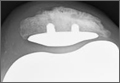
This Duracon patella has a porous-coated cobalt-chromium metal back intended for press-fit fixation, 3 cobalt-chromium porous-coated pegs, and a preassembled polyethylene anterior surface (Figure 1). Four sizes are available to fit the peripheral shape of the resected patella.
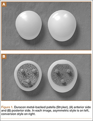
This patella has 3 styles: symmetric, asymmetric, and conversion. In this study, we used only the asymmetric and conversion styles. The design of each style incorporates medial/lateral facets intended to conform to the convex intercondylar radii of the femoral component, thereby allowing the patella to ride deeply in the recessed patellofemoral groove. The asymmetric patella is a resurfacing component with a generous polyethylene thickness (4.6 mm at its thinnest) and a larger lateral facet for more bone coverage. The asymmetric patella naturally medializes component placement. The articulating surface of the conversion patella is identical to that of the asymmetric patella. However, the conversion patella allows for exchange of the polyethylene portion of the implant without revising a stable, well-fixed metal baseplate.
Patient Selection
Candidates were recruited from a group of metal-backed patella patients within Dr. Hedley’s medical practice. All candidates had undergone primary total knee arthroplasty and received a Duracon press-fit metal-backed patella. All recruited patients had undergone primary knee arthroplasty at least 5 years before clinical and radiographic evaluation. Patients were included in the study if they had a diagnosis of noninflammatory degenerative joint disease (eg, osteoarthritis, traumatic arthritis, avascular necrosis). Patients with body mass index higher than 40 were excluded from the study.
Surgical Technique
The patella is everted completely or as much as feasible. Debridement is done circumferentially around the patella. Adherent fat and pseudomeniscus are stripped back until the surgeon sees the entry point of the quadriceps tendon fibers above and the patella tendon fibers below. The cut is then made at this level to remove as much bone as needed to restore the normal height of the patella with the implant in place. The cut is usually made by hand—without guides but with the patella stabilized with a towel clip above and below to prevent any movement during the action.
The desired cut must be absolutely planar, and this should be checked by placing the edge of the blade across the interface. Repeated passes with the saw blade are needed if the cut is not 100% planar. Once the cut is made, the patella is sized with the patella sizers and drill guide. After the appropriate size is selected, the patella is drilled with a bit that is slightly undersized from the size of the pegs (1/32 inch smaller than the bit supplied by the manufacturer).
Once the patella is prepared, the rest of the knee arthroplasty is performed. The patella is press-fit as the last component to be inserted.
Radiologic Review
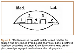
Radiographic analysis was performed by an independent reviewer according to the current Knee Society total knee arthroplasty roentgenographic evaluation and scoring system (Figure 2).16 The reviewer was an orthopedist specializing in hip and knee surgery. Radiographs the reviewer deemed questionable were shown to another independent hip and knee surgeon for validation. In all cases, the second reviewer confirmed the first reviewer’s initial recorded observations.
KSS (Knee Society Scale), WOMAC (Western Ontario and McMaster Universities Arthritis Index), and SF-36 (36-Item Short Form Health Survey) were also used to evaluate effectiveness in this protocol.
Survivorship Calculations
Kaplan-Meier survivorship was determined for all metal-backed patellae. For survival analysis, only knees with radiographic data were included (74 knees). Mean follow-up was 75.8 months (range, 60-105 months).
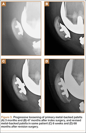
Seventy-four patients (88 knees) met the study criteria (Table). At minimum 5-year follow-up, complete data were acquired for 59 patients (72 knees). Of the total group, 14 knees did not have radiographic data. Those knees were categorized as lost to follow-up and were excluded from the survivorship analysis. The status of patients enrolled in the study at minimum 5-year follow-up is shown in the Table.
Mann-Whitney U test (nonparametric t test) was used to compare WOMAC and SF-36 scores between the “complete” and the “WOMAC and SF-36 only” data groups.
Statistical Analysis
Kaplan-Meier survivorship probabilities (asymmetric method) were calculated using SAS Version 9.2 (SAS Institute); 95% pointwise confidence limits were used.
The Mann-Whitney U test is a nonparametric analogue to the independent-samples t test. It was used here to compare WOMAC and SF-36 scores of patients with “complete” data with scores of patients with “WOMAC and SF-36 only” data. In either group, for patients who had primary bilateral knee arthroplasty, mean WOMAC and SF-36 scores were used.
Comparisons were made between the unilateral and bilateral knee arthroplasty groups. There were no differences in age, height, or weight (Mann-Whitney U test) or in sex, primary diagnosis, or number of patients lost to follow-up (Fisher exact test). Fisher exact test (vs χ2 test) was used for the contingency table analysis because of small cell sizes (eg, ≤10 females in ‘‘both knees” group), suggesting the unilateral and bilateral patients did not differ in demographics.
For all patient-reported questionnaires, bilateral patients were given the opportunity to note any differences between their knee arthroplasties, but none of these patients made any special notations. We interpreted this to mean that all survey responses from bilateral patients were applicable to both knee arthroplasties.
Results
Seventy-four patients (88 knees) were enrolled in the study: 31 women (41.2%) and 43 men (58.1%). At time of surgery, mean age was 59.7 years (range, 40-86 years), and mean body mass index was 30.6 (range, 19.1-39.6). Eighty-three knees were diagnosed with osteoarthritis, and 5 knees were diagnosed with posttraumatic arthritis. Mean time to follow-up was 74.8 months (range, 60-105 months). Fourteen knees (14 patients) were considered lost to follow-up. However, 8 patients (8 knees) were contacted by telephone about the status of their knee(s), and all 8 completed and returned the minimum 5-year follow-up WOMAC and SF-36 forms; they did not return for their minimum 5-year clinical or radiographic evaluations.
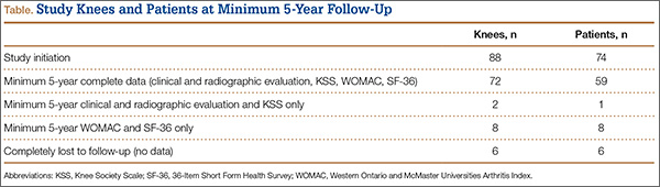
Asymmetric patellae were used in 24 knees, conversion patellae in 64 knees (88 knees total). Forty-nine months after surgery, 1 patella was revised for loosening at its interface with the bone. The 51-year-old active female patient’s asymmetric patella was revised to a conversion patella. The decision to implant another metal-backed device was based on its high density; proper intrusion of acrylic cement would have been questionable. Some early wear was observed on the tibial insert, which was replaced. Sixty-eight months after the revision, the patient was asymptomatic, with a KSS Pain score of 96 and a KSS Function score of 100 (Figure 3). Another revision, for tibial insert exchange only, was performed 48 months after surgery. During this revision, the patella was evaluated and found to be well fixed and functioning normally.
Survivorship of the Duracon metal-backed patella at minimum 5-year follow-up was estimated to be 93.95%, with bounds of 73.61% and 98.74%.
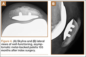
Radiographic analysis revealed no radiolucencies larger than 1 mm (Figure 4). Seventeen 1-mm radiolucencies were recorded: 6 (35.3%) in zone 1, 2 (11.8%) in zone 2, and 9 (52.9%) in zone 4. Twelve (70.6%) of the 17 radiolucencies were in the left knee. Nine radiolucencies were in women and 8 in men. Most (55.6%) of the women’s radiolucencies were in zone 1, and most (75.0%) of the men’s were in zone 4. There were no loose beads other than in the case that was later revised.
KSS, WOMAC, and SF-36 scores and radiographic reviews were used to evaluate effectiveness in accordance with the protocol. At minimum 5-year follow-up, mean KSS Pain score was 94.10 (range, 55-100), and mean KSS Function score was 92.67 (range, 60-100). Mean WOMAC score was 2.21 (range, 0-19.70), mean SF-36 Physical score was 83.65 (range, 30.70-100), and mean SF-36 Mental score was 89.41 (range, 1.4-100).
The preceding calculations do not include WOMAC and SF-36 data for the 8 patients (8 knees) who were counted as lost to follow-up but who submitted minimum 5-year follow-up data. We compared these 8 patients with the 60 patients (74 knees) who had complete WOMAC and SF-36 data at the end of the study in order to determine whether there were any statistically significant differences between the 2 groups’ mean scores. No statistically significant differences were detected in any WOMAC or SF-36 category (α = 0.05).
Discussion
Metal-backed patellar components were originally designed to address the shortcomings (eg, fracture, deformation, aseptic loosening) of cemented all-polyethylene patellae.1-3 It was thought that the stiffness of the metal could help resist polyethylene deformation and that the press-fit interface with bone might eliminate issues related to bone cement.8 However, short-term failures were reported with early metal-backed designs.9,10 At the same time, good fixation with bone ingrowth was observed in both titanium and cobalt-chromium porous-coated patellae.1,3,9-12,17 Further, reports of poor outcomes with some metal-backed patella designs overshadowed reports of positive outcomes.2,3 In all reports (of both poor and positive outcomes), component design, patellar tracking, and surgical technique were cited as contributing to implant success.2,3,14,17,18 Subsequent design improvements (eg, use of a third stabilizing peg, thicker polyethylene, improved conformity) produced excellent outcomes.8,12,15
Our early results are similar to those reported in the literature, and we observed markedly better outcomes that we think resulted from component design improvements. Over the past decade, this has been particularly true with our use of the Duracon metal-backed patella, which has thicker polyethylene, better articular conformity, and a third stabilizing peg, all of which were previously noted as contributing to a successful metal-backed patellar component.2,12,14,15,19 In our study, all 72 knees radiographically evaluated and independently reviewed at minimum 5-year follow-up had well-fixed press-fit metal-backed patellae. Seventeen patellae had 1-mm radiolucencies; the other 59 had no radiolucencies in any zone around the patella–bone interface.
One of the most important aspects of removing a metal-backed patellar component from a patella is that the remaining bone stock is often far superior to the stock available after revision of a cemented patella. Careful removal should leave an excellent bony bed for reimplantation.
We think that surgeons should adhere to certain indications and contraindications when implanting metal-backed patellae and that doing so can contribute to successful outcomes. Type of bone stock available should be considered, as successful biological fixation relies on a good blood supply. A dense (or thin) patella in which intrusion of acrylic cement is improbable or impossible may favor use of a metal-backed patella. Cement is not an adhesive but a grout, so successful cementation requires intrusion of cement into the interstices of the cancellous bone. As adequate intrusion of cement into dense bone is not possible, cementation may not be the best option. Some patellae have failed because of peg “shear-off,”9 likely caused not by failure of peg strength but by failure of cement fixation at the nonpeg interface.20,21 Polyethylene pegs fail when used as the sole method of fixation (they were never designed for that). In addition, we think younger patients are often indicated for a metal-backed patella because, over the long term, loosening of a cemented patella (and the accompanying stress shielding and osteolysis) may cause severe patellar bone destruction. Last, we have found that abnormally high or small patellae are not good candidates for cement fixation because they tend to work themselves loose riding on and off the superior flange. These types of patellae appear to have a much sturdier and longer lasting interface than cement, once biological fixation has occurred.
In summary, we think the indications for a metal-backed implant are a patella that is dense or sclerotic; a patella that is thin, abnormally high, or small; and a younger patient. In addition, a metal-backed implant is not indicated for soft, osteoporotic bone.
This study had a few limitations. Fourteen knees (14 patients), or 15.9% of all knees in the study, were categorized as lost to follow-up. Comparing the WOMAC and SF-36 scores of 8 patients (8 knees) who completed minimum 5-year follow-up but were not clinically evaluated with the scores of patients who had complete data, we found no statistically significant differences in any category. However, 5-year follow-up clinical data were available for those 8 patients. Nevertheless, 74 knees were available for radiologic evaluation, and during telephone interviews all 8 patients indicated they had their original implant(s) and were asymptomatic.
Our experience with the Duracon metal-backed patella has been encouraging. In the study reported here, there were no failures caused by dissociation of plastic. We think that, because the porous coating is under almost constant compression, biological fixation is likely in most instances, as observed in our minimum 5-year radiologic results. Given our minimum 5-year follow-up results with uncemented metal-backed patellae, we think their use may be a viable alternative to use of all-polyethylene patellae.
1. Firestone TP, Teeny SM, Krackow KA, Hungerford DS. The clinical and roentgenographic results of cementless porous-coated patellar fixation. Clin Orthop Relat Res. 1991;273:184-189.
2. Laskin RS, Bucknell A. The use of metal-backed patellar prostheses in total knee arthroplasty. Clin Orthop Relat Res. 1990;260:52-55.
3. Evanich CJ, Tkach TK, von Glinski S, Camargo MP, Hofmann AA. 6- to 10-year experience using countersunk metal-backed patellas. J Arthroplasty. 1997;12(2):149-154.
4. Schwartz AJ, Della Vale CJ, Rosenberg AG, Jacobs JJ, Berger RA, Galante JO. Cruciate-retaining TKA using a third-generation system with a four-pegged tibial component: a minimum 10-year followup note. Clin Orthop Relat Res. 2010;468(8):2160-2167.
5. Bisschop R, Brouwer RW, Van Raay JJ. Total knee arthroplasty in younger patients: a 13-year follow-up study. Orthopedics. 2010;33(12):876-880.
6. Dixon MC, Brown RR, Parsch D, Scott RD. Modular fixed-bearing total knee arthroplasty with retention of the posterior cruciate ligament. A study of patients followed for a minimum of fifteen years. J Bone Joint Surg Am. 2005;87(3):598-603.
7. Brick GW, Scott RD. The patellofemoral component of total knee arthroplasty. Clin Orthop Relat Res. 1988;231)163-178.
8. Garcia RM, Kraay MJ, Goldberg VM. Isolated all-polyethylene patellar revisions for metal-backed patellar failure. Clin Orthop Relat Res. 2008;466(11):2784-2789.
9. Rosenberg AG, Andriacchi TP, Barden R, Galante JO. Patellar component failure in cementless total knee arthroplasty. Clin Orthop Relat Res. 1988;(236):106-114.
10. Stulberg SD, Stulberg BN, Hamati Y, Tsao A. Failure mechanisms of metal-backed patellar components. Clin Orthop Relat Res. 1988;236:88-105.
11. Sundfeldt M, Johansson CB, Regner L, Albrektsson T, Carlsson LV. Long-term results of a cementless knee prosthesis with a metal-backed patellar component: clinical and radiological follow-up with histology from retrieved components. J Long Term Eff Med Implants. 2003;13(4):341-354.
12. Kraay MJ, Darr OJ, Salata MJ, Goldberg VM. Outcome of metal-backed cementless patellar components: the effect of implant design. Clin Orthop Relat Res. 2001;392:239-244.
13. Jensen LN, Lund B, Gotfredsen K. Bone growth into a revised porous-coated patellar implant. Acta Orthop Scand. 1990;61(3):213-216.
14. Hsu HP, Walker PS. Wear and deformation of patellar components in total knee arthroplasty. Clin Orthop Relat Res. 1989;246:260-265.
15. Jordan LR, Sorrells RB, Jordan LC, Olivo JL. The long-term results of a metal-backed mobile bearing patella. Clin Orthop Relat Res. 2005;436:111-118.
16. Ewald FC. The Knee Society total knee arthroplasty roentgenographic evaluation and scoring system. Clin Orthop Relat Res. 1989;248:9-12.
17. Bayley JC, Scott RD, Ewald FC, Holmes GB Jr. Failure of the metal-backed patellar component after total knee replacement. J Bone Joint Surg Am. 1988;70(5):668-674.
18. Lombardi AV Jr, Engh GA, Volz RG, Albrigo JL, Brainard BJ. Fracture/dissociation of the polyethylene in metal-backed patellar components in total knee arthroplasty. J Bone Joint Surg Am. 1988;70(5):675-679.
19. Moreland JR. Mechanisms of failure in total knee arthroplasty. Clin Orthop Relat Res. 1988;226:49-64.
20. Francke EI, Lachiewicz PF. Failure of a cemented all-polyethylene patellar component of a press-fit condylar total knee arthroplasty. J Arthroplasty. 2000;15(2):234-237.
21. Stulberg BN, Wright TM, Stoller AP, Mimnaugh KL, Mason JJ. Bilateral patellar component shear failure of highly cross-linked polyethylene components: report of a case and laboratory analysis of failure mechanisms. J Arthroplasty. 2012;27(5):789-796.
The metal-backed patella was originally designed to address the shortcomings of cemented, all-polyethylene patellae: deformation, aseptic loosening, stress fractures of polyethylene, and possible thermal damage from bone cement.1-3 Several long-term studies have found very good outcomes with use of all-polyethylene patellae.4-6 However, complications of using an all-polyethylene patella reportedly accounted for up to half of all knee revisions, and during revision surgery patellar bone stock was often found to have been compromised.7
The intention behind the design of press-fit metal-backed patellae was to address the shortcomings of all-polyethylene patellae by eliminating the need for bone cement and providing stiffness that would help resist polyethylene deformation while decreasing implant–bone interface stresses.8 However, early design iterations of metal-backed patellae demonstrated short-term failures—most commonly, local polyethylene wear damaging the locking mechanism and subsequent dissociation or fracture from the metal baseplate; polyethylene delamination from the metal baseplate; and failure of interface fixation.9,10 On the other hand, good fixation with bony ingrowth was observed in both titanium and cobalt-chromium porous-coated patellae.1,3,9,11-13 Overall, however, negative outcomes reported for metal-backed patellae led many surgeons to abandon these components and return to using cemented all-polyethylene patellae.
Negative outcomes of earlier metal-backed patellae designs have overshadowed reports of positive outcomes achieved with careful attention paid to component design, patellar tracking, and surgical technique.2,3,14 Subsequent design improvements (eg, a third stabilizing peg, thicker polyethylene, improved conformity) produced excellent outcomes.8,12,15 The advantages of using a metal-backed patella (eg, uniform load sharing, decreased polyethylene deformation, potential for biological fixation) may be unjustly outweighed by the fear of patellar component failure.3
Our 30-plus years of experience with metal-backed patellar components reflect the evolving effect of component design on outcome. Much as reported elsewhere, we found earlier component failures were caused by poor locking mechanisms, thin polyethylene, poor tracking, and minimal femur contact. Over the past decade, however, our outcomes with Duracon metal-backed patellae (Stryker) have been encouraging. We think these positive outcomes, seen over minimum 5-year follow-up, are largely attributable to the thicker polyethylene and improved articular conformity of this component relative to earlier designs. We have also found it helpful to adhere to certain criteria when implanting metal-backed patellae, and we think adhering to these criteria, along with improved component design, indicates use of press-fit metal-backed patellae. In this article, we report our failure incidence with use of this device at minimum 5-year follow-up.
Materials and Methods
In this single-center study, we performed clinical and independent radiographic reviews of 88 primary press-fit metal-backed patellae with minimum 5-year follow-up. All components were the same design (Duracon metal-backed patella) from the same manufacturer (Stryker).
This study, which began in September 2003, was reviewed and approved by the Western Institutional Review Board (WIRB). Either the investigator (Dr. Hedley) or the clinical study coordinator gave study candidates a full explanation of the study and answered any questions. Patients who still wanted to participate in the study signed WIRB consent forms after their index surgery but before minimum 5-year follow-up.
Device Description
This Duracon patella has a porous-coated cobalt-chromium metal back intended for press-fit fixation, 3 cobalt-chromium porous-coated pegs, and a preassembled polyethylene anterior surface (Figure 1). Four sizes are available to fit the peripheral shape of the resected patella.
This patella has 3 styles: symmetric, asymmetric, and conversion. In this study, we used only the asymmetric and conversion styles. The design of each style incorporates medial/lateral facets intended to conform to the convex intercondylar radii of the femoral component, thereby allowing the patella to ride deeply in the recessed patellofemoral groove. The asymmetric patella is a resurfacing component with a generous polyethylene thickness (4.6 mm at its thinnest) and a larger lateral facet for more bone coverage. The asymmetric patella naturally medializes component placement. The articulating surface of the conversion patella is identical to that of the asymmetric patella. However, the conversion patella allows for exchange of the polyethylene portion of the implant without revising a stable, well-fixed metal baseplate.
Patient Selection
Candidates were recruited from a group of metal-backed patella patients within Dr. Hedley’s medical practice. All candidates had undergone primary total knee arthroplasty and received a Duracon press-fit metal-backed patella. All recruited patients had undergone primary knee arthroplasty at least 5 years before clinical and radiographic evaluation. Patients were included in the study if they had a diagnosis of noninflammatory degenerative joint disease (eg, osteoarthritis, traumatic arthritis, avascular necrosis). Patients with body mass index higher than 40 were excluded from the study.
Surgical Technique
The patella is everted completely or as much as feasible. Debridement is done circumferentially around the patella. Adherent fat and pseudomeniscus are stripped back until the surgeon sees the entry point of the quadriceps tendon fibers above and the patella tendon fibers below. The cut is then made at this level to remove as much bone as needed to restore the normal height of the patella with the implant in place. The cut is usually made by hand—without guides but with the patella stabilized with a towel clip above and below to prevent any movement during the action.
The desired cut must be absolutely planar, and this should be checked by placing the edge of the blade across the interface. Repeated passes with the saw blade are needed if the cut is not 100% planar. Once the cut is made, the patella is sized with the patella sizers and drill guide. After the appropriate size is selected, the patella is drilled with a bit that is slightly undersized from the size of the pegs (1/32 inch smaller than the bit supplied by the manufacturer).
Once the patella is prepared, the rest of the knee arthroplasty is performed. The patella is press-fit as the last component to be inserted.
Radiologic Review
Radiographic analysis was performed by an independent reviewer according to the current Knee Society total knee arthroplasty roentgenographic evaluation and scoring system (Figure 2).16 The reviewer was an orthopedist specializing in hip and knee surgery. Radiographs the reviewer deemed questionable were shown to another independent hip and knee surgeon for validation. In all cases, the second reviewer confirmed the first reviewer’s initial recorded observations.
KSS (Knee Society Scale), WOMAC (Western Ontario and McMaster Universities Arthritis Index), and SF-36 (36-Item Short Form Health Survey) were also used to evaluate effectiveness in this protocol.
Survivorship Calculations
Kaplan-Meier survivorship was determined for all metal-backed patellae. For survival analysis, only knees with radiographic data were included (74 knees). Mean follow-up was 75.8 months (range, 60-105 months).
Seventy-four patients (88 knees) met the study criteria (Table). At minimum 5-year follow-up, complete data were acquired for 59 patients (72 knees). Of the total group, 14 knees did not have radiographic data. Those knees were categorized as lost to follow-up and were excluded from the survivorship analysis. The status of patients enrolled in the study at minimum 5-year follow-up is shown in the Table.
Mann-Whitney U test (nonparametric t test) was used to compare WOMAC and SF-36 scores between the “complete” and the “WOMAC and SF-36 only” data groups.
Statistical Analysis
Kaplan-Meier survivorship probabilities (asymmetric method) were calculated using SAS Version 9.2 (SAS Institute); 95% pointwise confidence limits were used.
The Mann-Whitney U test is a nonparametric analogue to the independent-samples t test. It was used here to compare WOMAC and SF-36 scores of patients with “complete” data with scores of patients with “WOMAC and SF-36 only” data. In either group, for patients who had primary bilateral knee arthroplasty, mean WOMAC and SF-36 scores were used.
Comparisons were made between the unilateral and bilateral knee arthroplasty groups. There were no differences in age, height, or weight (Mann-Whitney U test) or in sex, primary diagnosis, or number of patients lost to follow-up (Fisher exact test). Fisher exact test (vs χ2 test) was used for the contingency table analysis because of small cell sizes (eg, ≤10 females in ‘‘both knees” group), suggesting the unilateral and bilateral patients did not differ in demographics.
For all patient-reported questionnaires, bilateral patients were given the opportunity to note any differences between their knee arthroplasties, but none of these patients made any special notations. We interpreted this to mean that all survey responses from bilateral patients were applicable to both knee arthroplasties.
Results
Seventy-four patients (88 knees) were enrolled in the study: 31 women (41.2%) and 43 men (58.1%). At time of surgery, mean age was 59.7 years (range, 40-86 years), and mean body mass index was 30.6 (range, 19.1-39.6). Eighty-three knees were diagnosed with osteoarthritis, and 5 knees were diagnosed with posttraumatic arthritis. Mean time to follow-up was 74.8 months (range, 60-105 months). Fourteen knees (14 patients) were considered lost to follow-up. However, 8 patients (8 knees) were contacted by telephone about the status of their knee(s), and all 8 completed and returned the minimum 5-year follow-up WOMAC and SF-36 forms; they did not return for their minimum 5-year clinical or radiographic evaluations.
Asymmetric patellae were used in 24 knees, conversion patellae in 64 knees (88 knees total). Forty-nine months after surgery, 1 patella was revised for loosening at its interface with the bone. The 51-year-old active female patient’s asymmetric patella was revised to a conversion patella. The decision to implant another metal-backed device was based on its high density; proper intrusion of acrylic cement would have been questionable. Some early wear was observed on the tibial insert, which was replaced. Sixty-eight months after the revision, the patient was asymptomatic, with a KSS Pain score of 96 and a KSS Function score of 100 (Figure 3). Another revision, for tibial insert exchange only, was performed 48 months after surgery. During this revision, the patella was evaluated and found to be well fixed and functioning normally.
Survivorship of the Duracon metal-backed patella at minimum 5-year follow-up was estimated to be 93.95%, with bounds of 73.61% and 98.74%.
Radiographic analysis revealed no radiolucencies larger than 1 mm (Figure 4). Seventeen 1-mm radiolucencies were recorded: 6 (35.3%) in zone 1, 2 (11.8%) in zone 2, and 9 (52.9%) in zone 4. Twelve (70.6%) of the 17 radiolucencies were in the left knee. Nine radiolucencies were in women and 8 in men. Most (55.6%) of the women’s radiolucencies were in zone 1, and most (75.0%) of the men’s were in zone 4. There were no loose beads other than in the case that was later revised.
KSS, WOMAC, and SF-36 scores and radiographic reviews were used to evaluate effectiveness in accordance with the protocol. At minimum 5-year follow-up, mean KSS Pain score was 94.10 (range, 55-100), and mean KSS Function score was 92.67 (range, 60-100). Mean WOMAC score was 2.21 (range, 0-19.70), mean SF-36 Physical score was 83.65 (range, 30.70-100), and mean SF-36 Mental score was 89.41 (range, 1.4-100).
The preceding calculations do not include WOMAC and SF-36 data for the 8 patients (8 knees) who were counted as lost to follow-up but who submitted minimum 5-year follow-up data. We compared these 8 patients with the 60 patients (74 knees) who had complete WOMAC and SF-36 data at the end of the study in order to determine whether there were any statistically significant differences between the 2 groups’ mean scores. No statistically significant differences were detected in any WOMAC or SF-36 category (α = 0.05).
Discussion
Metal-backed patellar components were originally designed to address the shortcomings (eg, fracture, deformation, aseptic loosening) of cemented all-polyethylene patellae.1-3 It was thought that the stiffness of the metal could help resist polyethylene deformation and that the press-fit interface with bone might eliminate issues related to bone cement.8 However, short-term failures were reported with early metal-backed designs.9,10 At the same time, good fixation with bone ingrowth was observed in both titanium and cobalt-chromium porous-coated patellae.1,3,9-12,17 Further, reports of poor outcomes with some metal-backed patella designs overshadowed reports of positive outcomes.2,3 In all reports (of both poor and positive outcomes), component design, patellar tracking, and surgical technique were cited as contributing to implant success.2,3,14,17,18 Subsequent design improvements (eg, use of a third stabilizing peg, thicker polyethylene, improved conformity) produced excellent outcomes.8,12,15
Our early results are similar to those reported in the literature, and we observed markedly better outcomes that we think resulted from component design improvements. Over the past decade, this has been particularly true with our use of the Duracon metal-backed patella, which has thicker polyethylene, better articular conformity, and a third stabilizing peg, all of which were previously noted as contributing to a successful metal-backed patellar component.2,12,14,15,19 In our study, all 72 knees radiographically evaluated and independently reviewed at minimum 5-year follow-up had well-fixed press-fit metal-backed patellae. Seventeen patellae had 1-mm radiolucencies; the other 59 had no radiolucencies in any zone around the patella–bone interface.
One of the most important aspects of removing a metal-backed patellar component from a patella is that the remaining bone stock is often far superior to the stock available after revision of a cemented patella. Careful removal should leave an excellent bony bed for reimplantation.
We think that surgeons should adhere to certain indications and contraindications when implanting metal-backed patellae and that doing so can contribute to successful outcomes. Type of bone stock available should be considered, as successful biological fixation relies on a good blood supply. A dense (or thin) patella in which intrusion of acrylic cement is improbable or impossible may favor use of a metal-backed patella. Cement is not an adhesive but a grout, so successful cementation requires intrusion of cement into the interstices of the cancellous bone. As adequate intrusion of cement into dense bone is not possible, cementation may not be the best option. Some patellae have failed because of peg “shear-off,”9 likely caused not by failure of peg strength but by failure of cement fixation at the nonpeg interface.20,21 Polyethylene pegs fail when used as the sole method of fixation (they were never designed for that). In addition, we think younger patients are often indicated for a metal-backed patella because, over the long term, loosening of a cemented patella (and the accompanying stress shielding and osteolysis) may cause severe patellar bone destruction. Last, we have found that abnormally high or small patellae are not good candidates for cement fixation because they tend to work themselves loose riding on and off the superior flange. These types of patellae appear to have a much sturdier and longer lasting interface than cement, once biological fixation has occurred.
In summary, we think the indications for a metal-backed implant are a patella that is dense or sclerotic; a patella that is thin, abnormally high, or small; and a younger patient. In addition, a metal-backed implant is not indicated for soft, osteoporotic bone.
This study had a few limitations. Fourteen knees (14 patients), or 15.9% of all knees in the study, were categorized as lost to follow-up. Comparing the WOMAC and SF-36 scores of 8 patients (8 knees) who completed minimum 5-year follow-up but were not clinically evaluated with the scores of patients who had complete data, we found no statistically significant differences in any category. However, 5-year follow-up clinical data were available for those 8 patients. Nevertheless, 74 knees were available for radiologic evaluation, and during telephone interviews all 8 patients indicated they had their original implant(s) and were asymptomatic.
Our experience with the Duracon metal-backed patella has been encouraging. In the study reported here, there were no failures caused by dissociation of plastic. We think that, because the porous coating is under almost constant compression, biological fixation is likely in most instances, as observed in our minimum 5-year radiologic results. Given our minimum 5-year follow-up results with uncemented metal-backed patellae, we think their use may be a viable alternative to use of all-polyethylene patellae.
1. Firestone TP, Teeny SM, Krackow KA, Hungerford DS. The clinical and roentgenographic results of cementless porous-coated patellar fixation. Clin Orthop Relat Res. 1991;273:184-189.
2. Laskin RS, Bucknell A. The use of metal-backed patellar prostheses in total knee arthroplasty. Clin Orthop Relat Res. 1990;260:52-55.
3. Evanich CJ, Tkach TK, von Glinski S, Camargo MP, Hofmann AA. 6- to 10-year experience using countersunk metal-backed patellas. J Arthroplasty. 1997;12(2):149-154.
4. Schwartz AJ, Della Vale CJ, Rosenberg AG, Jacobs JJ, Berger RA, Galante JO. Cruciate-retaining TKA using a third-generation system with a four-pegged tibial component: a minimum 10-year followup note. Clin Orthop Relat Res. 2010;468(8):2160-2167.
5. Bisschop R, Brouwer RW, Van Raay JJ. Total knee arthroplasty in younger patients: a 13-year follow-up study. Orthopedics. 2010;33(12):876-880.
6. Dixon MC, Brown RR, Parsch D, Scott RD. Modular fixed-bearing total knee arthroplasty with retention of the posterior cruciate ligament. A study of patients followed for a minimum of fifteen years. J Bone Joint Surg Am. 2005;87(3):598-603.
7. Brick GW, Scott RD. The patellofemoral component of total knee arthroplasty. Clin Orthop Relat Res. 1988;231)163-178.
8. Garcia RM, Kraay MJ, Goldberg VM. Isolated all-polyethylene patellar revisions for metal-backed patellar failure. Clin Orthop Relat Res. 2008;466(11):2784-2789.
9. Rosenberg AG, Andriacchi TP, Barden R, Galante JO. Patellar component failure in cementless total knee arthroplasty. Clin Orthop Relat Res. 1988;(236):106-114.
10. Stulberg SD, Stulberg BN, Hamati Y, Tsao A. Failure mechanisms of metal-backed patellar components. Clin Orthop Relat Res. 1988;236:88-105.
11. Sundfeldt M, Johansson CB, Regner L, Albrektsson T, Carlsson LV. Long-term results of a cementless knee prosthesis with a metal-backed patellar component: clinical and radiological follow-up with histology from retrieved components. J Long Term Eff Med Implants. 2003;13(4):341-354.
12. Kraay MJ, Darr OJ, Salata MJ, Goldberg VM. Outcome of metal-backed cementless patellar components: the effect of implant design. Clin Orthop Relat Res. 2001;392:239-244.
13. Jensen LN, Lund B, Gotfredsen K. Bone growth into a revised porous-coated patellar implant. Acta Orthop Scand. 1990;61(3):213-216.
14. Hsu HP, Walker PS. Wear and deformation of patellar components in total knee arthroplasty. Clin Orthop Relat Res. 1989;246:260-265.
15. Jordan LR, Sorrells RB, Jordan LC, Olivo JL. The long-term results of a metal-backed mobile bearing patella. Clin Orthop Relat Res. 2005;436:111-118.
16. Ewald FC. The Knee Society total knee arthroplasty roentgenographic evaluation and scoring system. Clin Orthop Relat Res. 1989;248:9-12.
17. Bayley JC, Scott RD, Ewald FC, Holmes GB Jr. Failure of the metal-backed patellar component after total knee replacement. J Bone Joint Surg Am. 1988;70(5):668-674.
18. Lombardi AV Jr, Engh GA, Volz RG, Albrigo JL, Brainard BJ. Fracture/dissociation of the polyethylene in metal-backed patellar components in total knee arthroplasty. J Bone Joint Surg Am. 1988;70(5):675-679.
19. Moreland JR. Mechanisms of failure in total knee arthroplasty. Clin Orthop Relat Res. 1988;226:49-64.
20. Francke EI, Lachiewicz PF. Failure of a cemented all-polyethylene patellar component of a press-fit condylar total knee arthroplasty. J Arthroplasty. 2000;15(2):234-237.
21. Stulberg BN, Wright TM, Stoller AP, Mimnaugh KL, Mason JJ. Bilateral patellar component shear failure of highly cross-linked polyethylene components: report of a case and laboratory analysis of failure mechanisms. J Arthroplasty. 2012;27(5):789-796.
Transitions
This month will mark the end of my 10-year tenure as Editor-in-Chief of The American Journal of Orthopedics (AJO). Every successful organization goes through periodic transitions, where past successes are reviewed and future challenges addressed. AJO is no different. I would like to reflect on these past 10 years, share some highlights, and acknowledge those who have contributed to the success of AJO.
The Editorial Staff of the Journal has consistently performed beyond the call of duty, producing outstanding issues month after month. Of this excellent team, several members deserve special mention: Group Editor Glenn Williams, Managing Editor Joseph Kinsley, and Assistant Editor Kellie DeSantis. I offer my gratitude to all for a job well done.
I am particularly proud that under my leadership, the Editorial Board nearly doubled and clinical submissions increased almost 4-fold. I want to thank all members of the Editorial Board. Your expertise and dedication has enabled AJO to accommodate the vast increase in submissions and greatly improved the quality of papers published in recent years. I have so appreciated your efforts and hard work.
The addition of the Residency Advisory Board several years ago provided an excellent forum for orthopedic surgeons in training to share their thoughts on subjects of particular interest and address issues not typically covered during the course of their clinical training; such as the importance of mentorship, how to organize a practice, and how to decipher an employment contract for one’s first “real” job. I have been immensely impressed with residents’ insights and their willingness to share them with their colleagues. I hope that this experience at AJO will encourage them to join other Editorial Boards during their professional careers.
Over these past 10 years, I have tried to satisfy the mission of The American Journal of Orthopedics: “… to provide timely, practical, and readable technical information of the highest caliber to the orthopedic surgeon involved in the everyday practice of orthopedics.” To this end, I expanded the “expert opinion” 5 Points series originally introduced by John Gould, MD, my predecessor as Editor-in-Chief. In addition, I added the Practice Management articles, prepared by Karen Zupko and her associates, which have been especially informative and popular.
I have thoroughly enjoyed sharing with you my nonclinical editorials touching on the “topics of the day.” Among my favorites were “Customer Satisfaction: Are Hospitals ‘Hospitable’?”1 which anticipated the growing influence of patient satisfaction scores in our professional lives; and “Are Surgeons Accepting Bribes?”,2 addressing a subject that predated the 2007 Deferred Prosecution Agreement3 which has transformed the relationships between orthopedic surgeons and the orthopedic device industry. I hope you have enjoyed reading my musings as much as I enjoyed writing them.
Our incoming Editor-in-Chief is Bryan T. Hanypsiak, MD, Director of Sports Medicine, Peconic Bay Medical Center in Riverhead, New York, and Chairman of the September 2015 Innovative Techniques: The Knee Course, sponsored by AJO in Las Vegas. Bryan will remain committed to the original mission of AJO and its high editorial and peer reviewed standards. However, the format will change with the March 2016 issue and have the feel of a clinical magazine. I have every confidence that, with Dr. Hanypsiak’s leadership and the support of the publisher, the AJO brand will continue to thrive in an ever-changing and challenging marketplace.
Finally, I wish to thank all the readers of AJO who have supported the Journal, one of only a handful of orthopedic publications that still caters to the professional interests of the general orthopedic surgeon with a comprehensive scope of clinical and non-clinical topics. Leading the Board as Editor-in-Chief has been one of the most fulfilling and rewarding activities of my professional career, and it has truly been my honor to serve you. I wish all of you the best.
1. McCann PD. Customer satisfaction: are hospitals “hospitable”? Am J Orthop. 2006;35(2):59.
2. McCann PD. Are surgeons accepting bribes? Am J Orthop. 2006;35(3):114.
3. Five companies in hip and knee replacement industry avoid prosecution by agreeing to compliance rules and monitoring [press release]. US Department of Justice website. http://www.justice.gov/usao/nj/Press/files/pdffiles/Older/hips0927.rel.pdf. Published September 27, 2007. Accessed January 11, 2016.
This month will mark the end of my 10-year tenure as Editor-in-Chief of The American Journal of Orthopedics (AJO). Every successful organization goes through periodic transitions, where past successes are reviewed and future challenges addressed. AJO is no different. I would like to reflect on these past 10 years, share some highlights, and acknowledge those who have contributed to the success of AJO.
The Editorial Staff of the Journal has consistently performed beyond the call of duty, producing outstanding issues month after month. Of this excellent team, several members deserve special mention: Group Editor Glenn Williams, Managing Editor Joseph Kinsley, and Assistant Editor Kellie DeSantis. I offer my gratitude to all for a job well done.
I am particularly proud that under my leadership, the Editorial Board nearly doubled and clinical submissions increased almost 4-fold. I want to thank all members of the Editorial Board. Your expertise and dedication has enabled AJO to accommodate the vast increase in submissions and greatly improved the quality of papers published in recent years. I have so appreciated your efforts and hard work.
The addition of the Residency Advisory Board several years ago provided an excellent forum for orthopedic surgeons in training to share their thoughts on subjects of particular interest and address issues not typically covered during the course of their clinical training; such as the importance of mentorship, how to organize a practice, and how to decipher an employment contract for one’s first “real” job. I have been immensely impressed with residents’ insights and their willingness to share them with their colleagues. I hope that this experience at AJO will encourage them to join other Editorial Boards during their professional careers.
Over these past 10 years, I have tried to satisfy the mission of The American Journal of Orthopedics: “… to provide timely, practical, and readable technical information of the highest caliber to the orthopedic surgeon involved in the everyday practice of orthopedics.” To this end, I expanded the “expert opinion” 5 Points series originally introduced by John Gould, MD, my predecessor as Editor-in-Chief. In addition, I added the Practice Management articles, prepared by Karen Zupko and her associates, which have been especially informative and popular.
I have thoroughly enjoyed sharing with you my nonclinical editorials touching on the “topics of the day.” Among my favorites were “Customer Satisfaction: Are Hospitals ‘Hospitable’?”1 which anticipated the growing influence of patient satisfaction scores in our professional lives; and “Are Surgeons Accepting Bribes?”,2 addressing a subject that predated the 2007 Deferred Prosecution Agreement3 which has transformed the relationships between orthopedic surgeons and the orthopedic device industry. I hope you have enjoyed reading my musings as much as I enjoyed writing them.
Our incoming Editor-in-Chief is Bryan T. Hanypsiak, MD, Director of Sports Medicine, Peconic Bay Medical Center in Riverhead, New York, and Chairman of the September 2015 Innovative Techniques: The Knee Course, sponsored by AJO in Las Vegas. Bryan will remain committed to the original mission of AJO and its high editorial and peer reviewed standards. However, the format will change with the March 2016 issue and have the feel of a clinical magazine. I have every confidence that, with Dr. Hanypsiak’s leadership and the support of the publisher, the AJO brand will continue to thrive in an ever-changing and challenging marketplace.
Finally, I wish to thank all the readers of AJO who have supported the Journal, one of only a handful of orthopedic publications that still caters to the professional interests of the general orthopedic surgeon with a comprehensive scope of clinical and non-clinical topics. Leading the Board as Editor-in-Chief has been one of the most fulfilling and rewarding activities of my professional career, and it has truly been my honor to serve you. I wish all of you the best.
1. McCann PD. Customer satisfaction: are hospitals “hospitable”? Am J Orthop. 2006;35(2):59.
2. McCann PD. Are surgeons accepting bribes? Am J Orthop. 2006;35(3):114.
3. Five companies in hip and knee replacement industry avoid prosecution by agreeing to compliance rules and monitoring [press release]. US Department of Justice website. http://www.justice.gov/usao/nj/Press/files/pdffiles/Older/hips0927.rel.pdf. Published September 27, 2007. Accessed January 11, 2016.

Subpectoral Biceps Tenodesis
Tendinopathy of the long head of the biceps brachii (LHB) is a common source of anterior shoulder pain. The LHB tendon is an intra-articular yet extrasynovial structure, ensheathed by the synovial lining of the articular capsule.1 Branches of the anterior circumflex humeral artery course along the bicipital groove, but the gliding undersurface of the LHB remains avascular.2 Tendon irritation is most common within the groove and usually produces “tendinosis,” characterized by collagen fiber atrophy, fibrinoid necrosis, and fibrocyte proliferation.1 Neviaser and colleagues3 correlated such changes in the LHB tendon with rotator cuff pathology, as the 2 often coexist. Primary LHB tendinitis is less common and associated with younger patients who engage in overhead activities, such as baseball and volleyball.4
Nonoperative management, which is trialed initially, consists of rest, use of nonsteroidal anti-inflammatory drugs, and physical therapy. Corticosteroid injections are administered through the subacromial space or glenohumeral joint, which is continuous with the LHB sheath. Some physicians give ultrasound-guided injections into the LHB sheath. For fear of tendon atrophy from corticosteroid injections, some physicians prefer iontophoresis with a topical steroid over the bicipital groove. If conservative measures fail, the physician can choose from 2 primary surgical options: biceps tenotomy and tenodesis. Tenodesis can be performed within the groove (suprapectoral) or subpectoral. In this review, we highlight 5 key features of subpectoral biceps tenodesis to guide treatment and improve outcomes.
Examination and Indications
Management of LHB tendinopathy begins with a complete physical examination. Tenderness over the bicipital groove is the most consistent finding, but this region may be difficult to localize in large individuals. The arm should be internally rotated 10° to orient the groove anterior and palpated 7 cm below the acromion.5 Anterior shoulder pain after resisted elevation with the elbow extended and supinated represents a positive Speed test. A positive Yergason test produces pain with resisted forearm supination while the elbow is flexed to 90°.
Evaluation of biceps instability is important in deciding which type of management (operative or nonoperative) is appropriate for a patient. Medial biceps subluxation may be detected by bringing the flexed arm from abduction, external rotation into cross-body adduction, internal rotation with decreased arm flexion.6 Another maneuver that elicits biceps irritation is combined abduction–extension, which places tension on the biceps tendon. Similarly, coracoid impingement may disrupt the subscapularis roof of the biceps sheath and cause LHB instability. Dines and colleagues7 reproduced the painful clicking of coracoid impingement by placing the shoulder in forward elevation, internal rotation, and varying degrees of adduction. Belly-press, lift-off, and internal rotation strength are other tests that assess subscapularis integrity. Rotator cuff impingement signs should be evaluated, and the contralateral shoulder should be examined for comparison.
Plain radiographs may show a pathology, such as anterior acromial spurring or posterior overgrowth of the coracoid, for which surgery is more suited. T2-weighted magnetic resonance imaging (MRI) may show an increased LHB signal, but this has shown poor concordance with arthroscopic findings of biceps pathology.8 Magnetic resonance arthrography can better detect medial dislocation of the LHB tendon from subscapularis tears. Ultrasound is cost-effective but highly operator-dependent.
Indications for biceps tenotomy or tenodesis include failed conservative management, partial-thickness LHB tears more than 25% to 50% in diameter, and medial subluxation of the LHB tendon with or without a subscapularis tear. Superior labrum anterior to posterior (SLAP) tears in older patients are a relative indication. Intraoperative findings may also indicate the need for LHB surgery. During the diagnostic arthroscopy, the LHB tendon should be evaluated for synovial inflammation or fraying (Figures 1A, 1B). This may need to be done under dry conditions, as pump pressure can compress and blunt the inflamed appearance. The O’Brien maneuver can be performed to demonstrate incarceration of the LHB tendon within the anterior glenohumeral joint. A probe should be placed through an anterior portal to pull the intertubercular LHB tendon into view, as this region is most commonly inflamed (Figure 2). Probing of the tendon also allows assessment of the stability of the biceps sling.
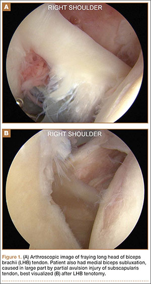
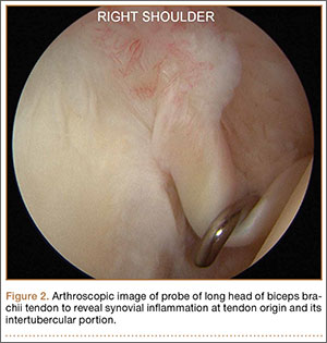
Surgical Technique
When biceps surgery is indicated, the surgeon must choose between tenotomy and tenodesis. Tenotomy is a low-demand procedure indicated for low-demand patients. A “Popeye” deformity may occur in up to 62% of patients, but Boileau and colleagues9 reported that none of their patients were bothered by it. Another concern after tenotomy is fatigue-cramping of the biceps muscle belly. Kelly and colleagues10 reported that up to 40% of patients had soreness and decreased strength with elbow flexion. Such cramping is more common in patients under age 60 years. For these reasons, biceps tenotomy should be reserved for older, low-demand patients who are not concerned about cosmesis and less likely to comply with postoperative motion restrictions.2 We tend to perform tenotomy in obese patients, who may have a Popeye deformity that is not detectable, and in patients with diabetes; the goal is to avoid a wound infection resulting from the close proximity of tenodesis incision and axilla.
Biceps tenodesis should preserve the length–tension relationship of the biceps muscle and maintain its normal contour. Tenodesis location may be proximal or distal. Proximal fixation can be performed arthroscopically, and its advocates argue that keeping the LHB tendon within the bicipital groove preserves muscle strength. Boileau and Neyton11 found biceps strength to be 90% that of the contralateral arm after arthroscopic tenodesis. The bicipital groove, however, is lined with synovium and is a primary site of LHB pathology. Up to 78% of intra-articular biceps tears extend through the groove outside the joint.12 Proximal tenodesis thus retains a major pain generator. In a retrospective study of 188 patients, Sanders and colleagues13,14 found a 36% revision rate after proximal arthroscopic tenodesis and a 13% rate after proximal open tenodesis with an intact biceps sheath—significantly lower than the 3% after distal tenodesis outside the bicipital groove.1 For this reason, we advocate distal biceps tenodesis beneath the pectoralis major tendon. After tenotomy with an arthroscopic basket (Figure 3), the LHB tendon is retracted out of the glenohumeral joint by extending the elbow. For the mini-open incision, the head of the bed is lowered from the beach-chair position to 30°. The arm is abducted on a Mayo stand, and the inferior border of the pectoralis major tendon is palpated. A 3-cm vertical incision is made along the medial arm starting 1 cm superior to the inferior pectoralis edge. The subcutaneous tissues are mobilized, and dissection is carried down to the pectoralis major and coracobrachialis tendons. Visualization of the cephalic vein indicates that the exposure is too far lateral. The horizontal fibers of the pectoralis major are identified, and a small incision through the inferior overlying fascia is directed laterally and then distally in line with the long axis of the humerus. Digital palpation helps identify the anterior humerus and fusiform LHB tendon running vertically within the intertubercular groove (Figure 4). Cephalad retraction of the pectoralis major allows direct visualization of the LHB tendon. A right-angle clamp is positioned deep to the LHB tendon and directed medial to lateral to retrieve the LHB tendon out of the incision.
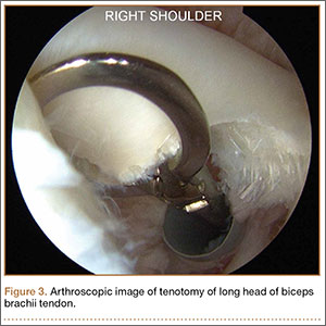
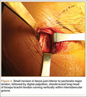
No. 2 looped Fiberwire (Arthrex) is then whip-stitched from the top of the myotendinous junction up 20 mm (Figure 5). The remaining 2 to 3 cm of LHB tendon proximal to the whip-stitching may be excised to remove inflammatory tissue. The pectoralis major is retracted superiorly with an Army-Navy retractor while a pointed Hohmann retractor is placed laterally. Medial retraction of the conjoined tendon should be done carefully with a Chandler elevator and minimal levering. In a cadaveric study, Dickens and colleagues15 found that the musculocutaneous nerve, radial nerve, and deep brachial artery were all within 1 cm of the standard medial retractor. Compared with internal rotation of the arm, external rotation moves the musculocutaneous nerve 11 mm farther from the tenodesis site.15
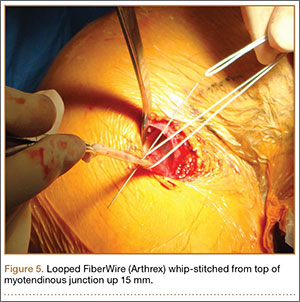
Once exposure is adequate, the appropriate length–tension of the LHB tendon must be established. The inferior edge of the pectoralis major is used as a landmark. Anatomical studies have shown that the top of the LHB myotendinous junction lies 20 to 31 mm proximal to the inferior pectoralis edge.16,17 Therefore, the tenodesis site should be 2 to 3 cm superior to the inferior pectoralis edge and centered on the humerus. Overall, the subpectoral location offers unique landmarks for LHB length-tensioning and provides soft-tissue coverage of the tenodesis site.
After identification of the appropriate tenodesis site, the surgeon chooses from a variety of fixation techniques. The “bone-tunnel technique” involves drilling an 8-mm unicortical hole through the anterior humerus followed by 2 smaller suture tunnels inferior to it; the LHB tendon with Krackow stitches is passed retrograde through the large hole by pulling the sutures through the smaller tunnels and tying them down.18 Despite the ease of performing this type of fixation, Mazzocca and colleagues19 found more cyclic displacement with bone tunnels than with interference screws and suture anchors. Other, less common techniques include the keyhole method (passing a rolled knot of LHB tendon through a keyhole in the bone)20 and soft-tissue tenodesis to the rotator interval or conjoined tendon.21,22 Recently, however, attention has turned mostly to interference screw and suture anchor fixation.
Multiple laboratory studies have demonstrated the superiority of interference screw fixation. Kilicoglu and colleagues23 and Ozalay and colleagues24 evaluated various fixation types in a sheep model, and both groups found the highest loads to failure with interference screws. Patzer and colleagues25 compared interference screws and knotless suture anchors in a human cadaveric study and noted significantly higher failure loads with interference screws. Some authors26,27 have presented conflicting laboratory data, and Millett and colleagues28 reported no difference in clinical outcomes between interference screws and suture anchors. However, these studies have not demonstrated inferiority of interference screws, and, in light of other evidence suggesting its biomechanical superiority, we prefer interference screw fixation.19,23-25,29
Exposing the bony surface for fixation involves electrocautery and subsequent use of a periosteal elevator to reflect a 1-cm periosteal window. A guide wire is drilled unicortically through the anterior cortex at the tenodesis site and is overreamed with an 8-mm cannulated reamer (Figure 6). This tunnel is then tapped, and bone debris is irrigated and suctioned from the wound. Cadaveric studies have shown no difference in failure loads with varying screw lengths or diameters.29,30 We use an 8×12-mm BioTenodesis screw (Arthrex) to match the typical width of the LHB tendon (Figures 7A-7C). One suture limb from the tendon whip-stitch is passed through the BioTenodesis screw and screwdriver. An assistant then uses a right-angle clamp as a pulley on the tendon so that the tendon may be visualized and “dunked” into the tunnel under direct visualization. As the screw is inserted, axial pressure is applied and the insertion paddle firmly held. Care should be taken to avoid overtightening the screw lest it become intramedullary. After the screw is flush to bone, the 2 whip-stitch suture limbs are tied for additional fixation.
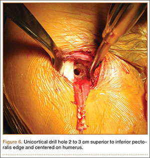
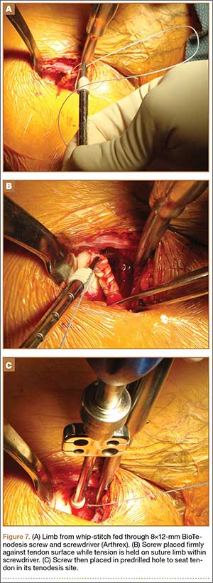
Postoperative Rehabilitation
The optimal postoperative protocol for subpectoral biceps tenodesis has not been rigorously studied and is guided by the procedures performed with the biceps tenodesis. For the immediate postoperative period, Provencher and colleagues5 and Mazzocca and colleagues31 recommended immobilization in a sling during sleep and during the day if the patient is out in public or having difficulty maintaining the elbow flexed passively.
For isolated biceps tenodesis cases, passive- and active-assisted range of motion (ROM) of the glenohumeral, elbow, and wrist joints are permitted during the initial 4 weeks. At 3 weeks, the sling is discontinued and active ROM permitted. At 6 weeks, strengthening of the biceps, rotator cuff, deltoid, and periscapular muscles may begin with isometric contractions and progress to elastic bands and handheld weights. The same protocol is used if acromioplasty is performed at time of tenodesis. These patients may progress to active-assisted and active ROM earlier than 4 weeks if advised of the risks. However, sustained isometric biceps contraction, biceps strengthening, and resisted supination should not be performed until 6 weeks after surgery. If rotator cuff repair is performed, the patient is immobilized in a sling and passive ROM of the glenohumeral, elbow, and wrist joints is permitted during the first 6 weeks. The patient may progress to active-assisted and active ROM over the next 6 weeks, after motion is restored but before formal strengthening is initiated.32 For overhead athletes, Werner and colleagues33 advocated a throwing program starting 3 to 4 months after surgery.
Outcomes and Complications
Mini-open subpectoral biceps tenodesis is a safe, reliable, and effective treatment for LHB tendon pathology. This procedure provides excellent pain relief and functional outcomes32,34,35 and has a low complication rate.5,35-40 At a mean of 29 months after biceps tenodesis with an interference screw, Mazzocca and colleagues32 found statistically significant improvements on all clinical outcome measures: Rowe, American Shoulder and Elbow Surgeons (ASES), Simple Shoulder Test (SST), Constant-Murley, and Single Assessment Numeric Evaluation (SANE). Biceps symmetry was restored in 35 of 41 patients. Millett and colleagues28 reported that subpectoral biceps tenodesis relieved pain and improved function as measured by visual analog scale pain, ASES scores, and abbreviated Constant scores. Werner and colleagues34 compared open subpectoral and arthroscopic suprapectoral techniques and found excellent clinical and functional outcomes with both techniques at a mean of 3.1 years. There were no significant differences in ROM, strength, or clinical outcome scores between the 2 techniques.
Potential complications include hematoma, seroma, hardware failure, reaction to biodegradable screw, persistent anterior shoulder pain, stiffness, humeral fracture, reflex sympathetic dystrophy, infection, nerve injury, and brachial artery injury. The musculocutaneous nerve can be lacerated during screw placement or even avulsed if the surgeon attempts to retrieve the LHB tendon blindly.41 In the most comprehensive study of tenodesis complications, Nho and colleagues35 recorded a 2% complication rate in 353 patients over 3 years. Persistent bicipital pain and fixation failure causing a Popeye deformity were the 2 most common complications (0.57% each). In a study of 103 patients, Abtahi and colleagues39 found a 7% complication rate, with 4 superficial wound infections and 2 temporary nerve palsies. Millett and colleagues28 reported low complication rates with both interference screw and suture anchor fixation. Neither technique had a fixation failure, and persistent bicipital groove tenderness occurred in just 3% of patients after interference screw fixation and in 7% after suture anchor fixation. Mazzocca and colleagues32 documented 1 fixation failure (2%) 1 year after interference screw fixation.
Werner and colleagues34 encountered stiffness more than any other complication and found it to be more common in their arthroscopic group (9.4%) than in their open group (6.0%). They used intra-articular corticosteroid injections and physical therapy to successfully treat all cases of postoperative stiffness. Humeral fracture is uncommon after tenodesis.37,42 In a recent biomechanical study, however, Euler and colleagues40 found a significant reduction (25%) in humeral strength after a laterally eccentric, malpositioned biceps tenodesis. This decreased osseous strength may increase susceptibility to humeral shaft fracture, especially when interference screw fixation is used. Sears and colleagues37 and Dein and colleagues42 presented case reports of humeral fracture after biceps tenodesis with an interference screw.
For patients with fixation failure or continued anterior shoulder pain, revision biceps tenodesis is safe and effective. Heckman and colleagues43 and Gregory and colleagues44 showed revision tenodesis can lead to excellent pain relief and functional outcomes, for it allows complete removal of the biceps from the groove and preserves biceps function. Gregory and colleagues44 revised subpectoral biceps tenodesis for either continued pain or fixation failure and found significant improvements in pain and function a mean of 33.4 months after surgery. Anthony and colleagues45 performed biceps tenodesis for failed surgical tenotomies and autorupture of the LHB tendon. In their study of 11 patients, this surgery resulted in symptom improvement, patient satisfaction, resolution of Popeye deformity, and predictable return to activity.
Conclusion
LHB tendon pathology is a significant source of anterior shoulder pain and functional limitation. Diagnosis and treatment of this pathology can be challenging, and it is important to identify any concomitant pathologies or other pain sources. After failed nonoperative management, surgeons have the option of mini-open subpectoral biceps tenodesis—a safe, reliable, and effective treatment with excellent outcomes. Although multiple fixation options are available, we think that, based on the current literature, fixation with a bioabsorbable interference screw remains the best option. This procedure has demonstrated efficacy for revision biceps tenodesis, failed biceps tenotomy, and autorupture of the biceps.
1. Friedman DJ, Dunn JC, Higgins LD, Warner JJP. Proximal biceps tendon: injuries and management. Sports Med Arthrosc. 2008;16(3):162-169.
2. Nho SJ, Strauss EJ, Lenart BA, et al. Long head of the biceps tendinopathy: diagnosis and management. J Am Acad Orthop Surg. 2010;18(11):645-656.
3. Neviaser TJ, Neviaser RJ, Neviaser JS, Neviaser JS. The four-in-one arthroplasty for the painful arc syndrome. Clin Orthop Relat Res. 1982;163:107-112.
4. Patton WC, McCluskey GM 3rd. Biceps tendinitis and subluxation. Clin Sports Med. 2001;20(3):505-529.
5. Provencher MT, LeClere LE, Romeo AA. Subpectoral biceps tenodesis. Sports Med Arthrosc. 2008;16(3):170-176.
6. Bennett WF. Arthroscopic repair of isolated subscapularis tears: a prospective cohort with 2- to 4-year follow-up. Arthroscopy. 2003;19(2):131-143.
7. Dines DM, Warren RF, Inglis AE, Pavlov H. The coracoid impingement syndrome. Bone Joint J Br. 1990;72(2):314-316.
8. Mohtadi NG, Vellet AD, Clark ML, et al. A prospective, double-blind comparison of magnetic resonance imaging and arthroscopy in the evaluation of patients presenting with shoulder pain. J Shoulder Elbow Surg. 2004;13(3):258-265.
9. Boileau P, Baqué F, Valerio L, Ahrens P, Chuinard C, Trojani C. Isolated arthroscopic biceps tenotomy or tenodesis improves symptoms in patients with massive irreparable rotator cuff tears. J Bone Joint Surg Am. 2007;89(4):747-757.
10. Kelly AM, Drakos MC, Fealy S, Taylor SA, O’Brien SJ. Arthroscopic release of the long head of the biceps tendon: functional outcome and clinical results. Am J Sports Med. 2005;33(2):208-213.
11. Boileau P, Neyton L. Arthroscopic tenodesis for lesions of the long head of the biceps. Oper Orthop Traumatol. 2005;17(6):601-623.
12. Moon SC, Cho NS, Rhee YG. Analysis of “hidden lesions” of the extra-articular biceps after subpectoral biceps tenodesis: the subpectoral portion as the optimal tenodesis site. Am J Sports Med. 2015;43(1):63-68.
13. Sanders B, Lavery K, Pennington S, Warner JJP. Biceps tendon tenodesis: success with proximal versus distal fixation (SS-16). Arthroscopy. 2008;24(6 suppl):e9.
14. Sanders B, Lavery KP, Pennington S, Warner JJ. Clinical success of biceps tenodesis with and without release of the transverse humeral ligament. J Shoulder Elbow Surg. 2012;21(1):66-71.
15. Dickens JF, Kilcoyne KG, Tintle SM, Giuliani J, Schaefer RA, Rue JP. Subpectoral biceps tenodesis: an anatomic study and evaluation of at-risk structures. Am J Sports Med. 2012;40(10):2337-2341.
16. Denard PJ, Dai X, Hanypsiak BT, Burkhart SS. Anatomy of the biceps tendon: implications for restoring physiological length–tension relation during biceps tenodesis with interference screw fixation. Arthroscopy. 2012;28(10):1352-1358.
17. Jarrett CD, McClelland WB, Xerogeanes JW. Minimally invasive proximal biceps tenodesis: an anatomical study for optimal placement and safe surgical technique. J Shoulder Elbow Surg. 2011;20(3):477-480.
18. Mazzocca AD, Noerdlinger MA, Romeo AA. Mini open and subpectoral biceps tenodesis. Oper Tech Sports Med. 2003;11(1):24-31.
19. Mazzocca AD, Bicos J, Santangelo S, Romeo AA, Arciero RA. The biomechanical evaluation of four fixation techniques for proximal biceps tenodesis. Arthroscopy. 2005;21(11):1296-1306.
20. Froimson AI, O I. Keyhole tenodesis of biceps origin at the shoulder. Clin Orthop Relat Res. 1975;(112):245-249.
21. Sekiya JK, Elkousy HA, Rodosky MW. Arthroscopic biceps tenodesis using the percutaneous intra-articular transtendon technique. Arthroscopy. 2003;19(10):1137-1141.
22. Verma NN, Drakos M, O’Brien SJ. Arthroscopic transfer of the long head biceps to the conjoint tendon. Arthroscopy. 2005;21(6):764.
23. Kilicoglu O, Koyuncu O, Demirhan M, et al. Time-dependent changes in failure loads of 3 biceps tenodesis techniques: in vivo study in a sheep model. Am J Sports Med. 2005;33(10):1536-1544.
24. Ozalay M, Akpinar S, Karaeminogullari O, et al. Mechanical strength of four different biceps tenodesis techniques. Arthroscopy. 2005;21(8):992-998.
25. Patzer T, Santo G, Olender GD, Wellmann M, Hurschler C, Schofer MD. Suprapectoral or subpectoral position for biceps tenodesis: biomechanical comparison of four different techniques in both positions. J Shoulder Elbow Surg. 2012;21(1):116-125.
26. Buchholz A, Martetschläger F, Siebenlist S, et al. Biomechanical comparison of intramedullary cortical button fixation and interference screw technique for subpectoral biceps tenodesis. Arthroscopy. 2013;29(5):845-853.
27. Tashjian RZ, Henninger HB. Biomechanical evaluation of subpectoral biceps tenodesis: dual suture anchor versus interference screw fixation. J Shoulder Elbow Surg. 2013;22(10):1408-1412.
28. Millett PJ, Sanders B, Gobezie R, Braun S, Warner JJP. Interference screw vs. suture anchor fixation for open subpectoral biceps tenodesis: does it matter? BMC Musculoskelet Disord. 2008;9(1):121.
29. Sethi PM, Rajaram A, Beitzel K, Hackett TR, Chowaniec DM, Mazzocca AD. Biomechanical performance of subpectoral biceps tenodesis: a comparison of interference screw fixation, cortical button fixation, and interference screw diameter. J Shoulder Elbow Surg. 2013;22(4):451-457.
30. Slabaugh MA, Frank RM, Van Thiel GS, et al. Biceps tenodesis with interference screw fixation: a biomechanical comparison of screw length and diameter. Arthroscopy. 2011;27(2):161-166.
31. Mazzocca AD, Rios CG, Romeo AA, Arciero RA. Subpectoral biceps tenodesis with interference screw fixation. Arthroscopy. 2005;21(7):896.
32. Mazzocca AD, Cote MP, Arciero CL, Romeo AA, Arciero RA. Clinical outcomes after subpectoral biceps tenodesis with an interference screw. Am J Sports Med. 2008;36(10):1922-1929.
33. Werner BC, Brockmeier SF, Miller MD. Etiology, diagnosis, and management of failed SLAP repair. J Am Acad Orthop Surg. 2014;22(9):554-565.
34. Werner BC, Evans CL, Holzgrefe RE, et al. Arthroscopic suprapectoral and open subpectoral biceps tenodesis: a comparison of minimum 2-year clinical outcomes. Am J Sports Med. 2014;42(11):2583-2590.
35. Nho SJ, Reiff SN, Verma NN, Slabaugh MA, Mazzocca AD, Romeo AA. Complications associated with subpectoral biceps tenodesis: low rates of incidence following surgery. J Shoulder Elbow Surg. 2010;19(5):764-768.
36. Rhee PC, Spinner RJ, Bishop AT, Shin AY. Iatrogenic brachial plexus injuries associated with open subpectoral biceps tenodesis: a report of 4 cases. Am J Sports Med. 2013;41(9):2048-2053.
37. Sears BW, Spencer EE, Getz CL. Humeral fracture following subpectoral biceps tenodesis in 2 active, healthy patients. J Shoulder Elbow Surg. 2011;20(6):e7-e11.
38. Ding DY, Gupta A, Snir N, Wolfson T, Meislin RJ. Nerve proximity during bicortical drilling for subpectoral biceps tenodesis: a cadaveric study. Arthroscopy. 2014;30(8):942-946.
39. Abtahi AM, Granger EK, Tashjian RZ. Complications after subpectoral biceps tenodesis using a dual suture anchor technique. Int J Shoulder Surg. 2014;8(2):47-50.
40. Euler SA, Smith SD, Williams BT, Dornan GJ, Millett PJ, Wijdicks CA. Biomechanical analysis of subpectoral biceps tenodesis: effect of screw malpositioning on proximal humeral strength. Am J Sports Med. 2015;43(1):69-74.
41. Carofino BC, Brogan DM, Kircher MF, et al. Iatrogenic nerve injuries during shoulder surgery. J Bone Joint Surg Am. 2013;95(18):1667-1674.
42. Dein EJ, Huri G, Gordon JC, McFarland EG. A humerus fracture in a baseball pitcher after biceps tenodesis. Am J Sports Med. 2014;42(4):877-879.
43. Heckman DS, Creighton RA, Romeo AA. Management of failed biceps tenodesis or tenotomy: causation and treatment. Sports Med Arthrosc. 2010;18(3):173-180.
44. Gregory JM, Harwood DP, Gochanour E, Sherman SL, Romeo AA. Clinical outcomes of revision biceps tenodesis. Int J Shoulder Surg. 2012;6(2):45-50.
45. Anthony SG, McCormick F, Gross DJ, Golijanin P, Provencher MT. Biceps tenodesis for long head of the biceps after auto-rupture or failed surgical tenotomy: results in an active population. J Shoulder Elbow Surg. 2015;24(2):e36-e40.
Tendinopathy of the long head of the biceps brachii (LHB) is a common source of anterior shoulder pain. The LHB tendon is an intra-articular yet extrasynovial structure, ensheathed by the synovial lining of the articular capsule.1 Branches of the anterior circumflex humeral artery course along the bicipital groove, but the gliding undersurface of the LHB remains avascular.2 Tendon irritation is most common within the groove and usually produces “tendinosis,” characterized by collagen fiber atrophy, fibrinoid necrosis, and fibrocyte proliferation.1 Neviaser and colleagues3 correlated such changes in the LHB tendon with rotator cuff pathology, as the 2 often coexist. Primary LHB tendinitis is less common and associated with younger patients who engage in overhead activities, such as baseball and volleyball.4
Nonoperative management, which is trialed initially, consists of rest, use of nonsteroidal anti-inflammatory drugs, and physical therapy. Corticosteroid injections are administered through the subacromial space or glenohumeral joint, which is continuous with the LHB sheath. Some physicians give ultrasound-guided injections into the LHB sheath. For fear of tendon atrophy from corticosteroid injections, some physicians prefer iontophoresis with a topical steroid over the bicipital groove. If conservative measures fail, the physician can choose from 2 primary surgical options: biceps tenotomy and tenodesis. Tenodesis can be performed within the groove (suprapectoral) or subpectoral. In this review, we highlight 5 key features of subpectoral biceps tenodesis to guide treatment and improve outcomes.
Examination and Indications
Management of LHB tendinopathy begins with a complete physical examination. Tenderness over the bicipital groove is the most consistent finding, but this region may be difficult to localize in large individuals. The arm should be internally rotated 10° to orient the groove anterior and palpated 7 cm below the acromion.5 Anterior shoulder pain after resisted elevation with the elbow extended and supinated represents a positive Speed test. A positive Yergason test produces pain with resisted forearm supination while the elbow is flexed to 90°.
Evaluation of biceps instability is important in deciding which type of management (operative or nonoperative) is appropriate for a patient. Medial biceps subluxation may be detected by bringing the flexed arm from abduction, external rotation into cross-body adduction, internal rotation with decreased arm flexion.6 Another maneuver that elicits biceps irritation is combined abduction–extension, which places tension on the biceps tendon. Similarly, coracoid impingement may disrupt the subscapularis roof of the biceps sheath and cause LHB instability. Dines and colleagues7 reproduced the painful clicking of coracoid impingement by placing the shoulder in forward elevation, internal rotation, and varying degrees of adduction. Belly-press, lift-off, and internal rotation strength are other tests that assess subscapularis integrity. Rotator cuff impingement signs should be evaluated, and the contralateral shoulder should be examined for comparison.
Plain radiographs may show a pathology, such as anterior acromial spurring or posterior overgrowth of the coracoid, for which surgery is more suited. T2-weighted magnetic resonance imaging (MRI) may show an increased LHB signal, but this has shown poor concordance with arthroscopic findings of biceps pathology.8 Magnetic resonance arthrography can better detect medial dislocation of the LHB tendon from subscapularis tears. Ultrasound is cost-effective but highly operator-dependent.
Indications for biceps tenotomy or tenodesis include failed conservative management, partial-thickness LHB tears more than 25% to 50% in diameter, and medial subluxation of the LHB tendon with or without a subscapularis tear. Superior labrum anterior to posterior (SLAP) tears in older patients are a relative indication. Intraoperative findings may also indicate the need for LHB surgery. During the diagnostic arthroscopy, the LHB tendon should be evaluated for synovial inflammation or fraying (Figures 1A, 1B). This may need to be done under dry conditions, as pump pressure can compress and blunt the inflamed appearance. The O’Brien maneuver can be performed to demonstrate incarceration of the LHB tendon within the anterior glenohumeral joint. A probe should be placed through an anterior portal to pull the intertubercular LHB tendon into view, as this region is most commonly inflamed (Figure 2). Probing of the tendon also allows assessment of the stability of the biceps sling.
Surgical Technique
When biceps surgery is indicated, the surgeon must choose between tenotomy and tenodesis. Tenotomy is a low-demand procedure indicated for low-demand patients. A “Popeye” deformity may occur in up to 62% of patients, but Boileau and colleagues9 reported that none of their patients were bothered by it. Another concern after tenotomy is fatigue-cramping of the biceps muscle belly. Kelly and colleagues10 reported that up to 40% of patients had soreness and decreased strength with elbow flexion. Such cramping is more common in patients under age 60 years. For these reasons, biceps tenotomy should be reserved for older, low-demand patients who are not concerned about cosmesis and less likely to comply with postoperative motion restrictions.2 We tend to perform tenotomy in obese patients, who may have a Popeye deformity that is not detectable, and in patients with diabetes; the goal is to avoid a wound infection resulting from the close proximity of tenodesis incision and axilla.
Biceps tenodesis should preserve the length–tension relationship of the biceps muscle and maintain its normal contour. Tenodesis location may be proximal or distal. Proximal fixation can be performed arthroscopically, and its advocates argue that keeping the LHB tendon within the bicipital groove preserves muscle strength. Boileau and Neyton11 found biceps strength to be 90% that of the contralateral arm after arthroscopic tenodesis. The bicipital groove, however, is lined with synovium and is a primary site of LHB pathology. Up to 78% of intra-articular biceps tears extend through the groove outside the joint.12 Proximal tenodesis thus retains a major pain generator. In a retrospective study of 188 patients, Sanders and colleagues13,14 found a 36% revision rate after proximal arthroscopic tenodesis and a 13% rate after proximal open tenodesis with an intact biceps sheath—significantly lower than the 3% after distal tenodesis outside the bicipital groove.1 For this reason, we advocate distal biceps tenodesis beneath the pectoralis major tendon. After tenotomy with an arthroscopic basket (Figure 3), the LHB tendon is retracted out of the glenohumeral joint by extending the elbow. For the mini-open incision, the head of the bed is lowered from the beach-chair position to 30°. The arm is abducted on a Mayo stand, and the inferior border of the pectoralis major tendon is palpated. A 3-cm vertical incision is made along the medial arm starting 1 cm superior to the inferior pectoralis edge. The subcutaneous tissues are mobilized, and dissection is carried down to the pectoralis major and coracobrachialis tendons. Visualization of the cephalic vein indicates that the exposure is too far lateral. The horizontal fibers of the pectoralis major are identified, and a small incision through the inferior overlying fascia is directed laterally and then distally in line with the long axis of the humerus. Digital palpation helps identify the anterior humerus and fusiform LHB tendon running vertically within the intertubercular groove (Figure 4). Cephalad retraction of the pectoralis major allows direct visualization of the LHB tendon. A right-angle clamp is positioned deep to the LHB tendon and directed medial to lateral to retrieve the LHB tendon out of the incision.
No. 2 looped Fiberwire (Arthrex) is then whip-stitched from the top of the myotendinous junction up 20 mm (Figure 5). The remaining 2 to 3 cm of LHB tendon proximal to the whip-stitching may be excised to remove inflammatory tissue. The pectoralis major is retracted superiorly with an Army-Navy retractor while a pointed Hohmann retractor is placed laterally. Medial retraction of the conjoined tendon should be done carefully with a Chandler elevator and minimal levering. In a cadaveric study, Dickens and colleagues15 found that the musculocutaneous nerve, radial nerve, and deep brachial artery were all within 1 cm of the standard medial retractor. Compared with internal rotation of the arm, external rotation moves the musculocutaneous nerve 11 mm farther from the tenodesis site.15
Once exposure is adequate, the appropriate length–tension of the LHB tendon must be established. The inferior edge of the pectoralis major is used as a landmark. Anatomical studies have shown that the top of the LHB myotendinous junction lies 20 to 31 mm proximal to the inferior pectoralis edge.16,17 Therefore, the tenodesis site should be 2 to 3 cm superior to the inferior pectoralis edge and centered on the humerus. Overall, the subpectoral location offers unique landmarks for LHB length-tensioning and provides soft-tissue coverage of the tenodesis site.
After identification of the appropriate tenodesis site, the surgeon chooses from a variety of fixation techniques. The “bone-tunnel technique” involves drilling an 8-mm unicortical hole through the anterior humerus followed by 2 smaller suture tunnels inferior to it; the LHB tendon with Krackow stitches is passed retrograde through the large hole by pulling the sutures through the smaller tunnels and tying them down.18 Despite the ease of performing this type of fixation, Mazzocca and colleagues19 found more cyclic displacement with bone tunnels than with interference screws and suture anchors. Other, less common techniques include the keyhole method (passing a rolled knot of LHB tendon through a keyhole in the bone)20 and soft-tissue tenodesis to the rotator interval or conjoined tendon.21,22 Recently, however, attention has turned mostly to interference screw and suture anchor fixation.
Multiple laboratory studies have demonstrated the superiority of interference screw fixation. Kilicoglu and colleagues23 and Ozalay and colleagues24 evaluated various fixation types in a sheep model, and both groups found the highest loads to failure with interference screws. Patzer and colleagues25 compared interference screws and knotless suture anchors in a human cadaveric study and noted significantly higher failure loads with interference screws. Some authors26,27 have presented conflicting laboratory data, and Millett and colleagues28 reported no difference in clinical outcomes between interference screws and suture anchors. However, these studies have not demonstrated inferiority of interference screws, and, in light of other evidence suggesting its biomechanical superiority, we prefer interference screw fixation.19,23-25,29
Exposing the bony surface for fixation involves electrocautery and subsequent use of a periosteal elevator to reflect a 1-cm periosteal window. A guide wire is drilled unicortically through the anterior cortex at the tenodesis site and is overreamed with an 8-mm cannulated reamer (Figure 6). This tunnel is then tapped, and bone debris is irrigated and suctioned from the wound. Cadaveric studies have shown no difference in failure loads with varying screw lengths or diameters.29,30 We use an 8×12-mm BioTenodesis screw (Arthrex) to match the typical width of the LHB tendon (Figures 7A-7C). One suture limb from the tendon whip-stitch is passed through the BioTenodesis screw and screwdriver. An assistant then uses a right-angle clamp as a pulley on the tendon so that the tendon may be visualized and “dunked” into the tunnel under direct visualization. As the screw is inserted, axial pressure is applied and the insertion paddle firmly held. Care should be taken to avoid overtightening the screw lest it become intramedullary. After the screw is flush to bone, the 2 whip-stitch suture limbs are tied for additional fixation.
Postoperative Rehabilitation
The optimal postoperative protocol for subpectoral biceps tenodesis has not been rigorously studied and is guided by the procedures performed with the biceps tenodesis. For the immediate postoperative period, Provencher and colleagues5 and Mazzocca and colleagues31 recommended immobilization in a sling during sleep and during the day if the patient is out in public or having difficulty maintaining the elbow flexed passively.
For isolated biceps tenodesis cases, passive- and active-assisted range of motion (ROM) of the glenohumeral, elbow, and wrist joints are permitted during the initial 4 weeks. At 3 weeks, the sling is discontinued and active ROM permitted. At 6 weeks, strengthening of the biceps, rotator cuff, deltoid, and periscapular muscles may begin with isometric contractions and progress to elastic bands and handheld weights. The same protocol is used if acromioplasty is performed at time of tenodesis. These patients may progress to active-assisted and active ROM earlier than 4 weeks if advised of the risks. However, sustained isometric biceps contraction, biceps strengthening, and resisted supination should not be performed until 6 weeks after surgery. If rotator cuff repair is performed, the patient is immobilized in a sling and passive ROM of the glenohumeral, elbow, and wrist joints is permitted during the first 6 weeks. The patient may progress to active-assisted and active ROM over the next 6 weeks, after motion is restored but before formal strengthening is initiated.32 For overhead athletes, Werner and colleagues33 advocated a throwing program starting 3 to 4 months after surgery.
Outcomes and Complications
Mini-open subpectoral biceps tenodesis is a safe, reliable, and effective treatment for LHB tendon pathology. This procedure provides excellent pain relief and functional outcomes32,34,35 and has a low complication rate.5,35-40 At a mean of 29 months after biceps tenodesis with an interference screw, Mazzocca and colleagues32 found statistically significant improvements on all clinical outcome measures: Rowe, American Shoulder and Elbow Surgeons (ASES), Simple Shoulder Test (SST), Constant-Murley, and Single Assessment Numeric Evaluation (SANE). Biceps symmetry was restored in 35 of 41 patients. Millett and colleagues28 reported that subpectoral biceps tenodesis relieved pain and improved function as measured by visual analog scale pain, ASES scores, and abbreviated Constant scores. Werner and colleagues34 compared open subpectoral and arthroscopic suprapectoral techniques and found excellent clinical and functional outcomes with both techniques at a mean of 3.1 years. There were no significant differences in ROM, strength, or clinical outcome scores between the 2 techniques.
Potential complications include hematoma, seroma, hardware failure, reaction to biodegradable screw, persistent anterior shoulder pain, stiffness, humeral fracture, reflex sympathetic dystrophy, infection, nerve injury, and brachial artery injury. The musculocutaneous nerve can be lacerated during screw placement or even avulsed if the surgeon attempts to retrieve the LHB tendon blindly.41 In the most comprehensive study of tenodesis complications, Nho and colleagues35 recorded a 2% complication rate in 353 patients over 3 years. Persistent bicipital pain and fixation failure causing a Popeye deformity were the 2 most common complications (0.57% each). In a study of 103 patients, Abtahi and colleagues39 found a 7% complication rate, with 4 superficial wound infections and 2 temporary nerve palsies. Millett and colleagues28 reported low complication rates with both interference screw and suture anchor fixation. Neither technique had a fixation failure, and persistent bicipital groove tenderness occurred in just 3% of patients after interference screw fixation and in 7% after suture anchor fixation. Mazzocca and colleagues32 documented 1 fixation failure (2%) 1 year after interference screw fixation.
Werner and colleagues34 encountered stiffness more than any other complication and found it to be more common in their arthroscopic group (9.4%) than in their open group (6.0%). They used intra-articular corticosteroid injections and physical therapy to successfully treat all cases of postoperative stiffness. Humeral fracture is uncommon after tenodesis.37,42 In a recent biomechanical study, however, Euler and colleagues40 found a significant reduction (25%) in humeral strength after a laterally eccentric, malpositioned biceps tenodesis. This decreased osseous strength may increase susceptibility to humeral shaft fracture, especially when interference screw fixation is used. Sears and colleagues37 and Dein and colleagues42 presented case reports of humeral fracture after biceps tenodesis with an interference screw.
For patients with fixation failure or continued anterior shoulder pain, revision biceps tenodesis is safe and effective. Heckman and colleagues43 and Gregory and colleagues44 showed revision tenodesis can lead to excellent pain relief and functional outcomes, for it allows complete removal of the biceps from the groove and preserves biceps function. Gregory and colleagues44 revised subpectoral biceps tenodesis for either continued pain or fixation failure and found significant improvements in pain and function a mean of 33.4 months after surgery. Anthony and colleagues45 performed biceps tenodesis for failed surgical tenotomies and autorupture of the LHB tendon. In their study of 11 patients, this surgery resulted in symptom improvement, patient satisfaction, resolution of Popeye deformity, and predictable return to activity.
Conclusion
LHB tendon pathology is a significant source of anterior shoulder pain and functional limitation. Diagnosis and treatment of this pathology can be challenging, and it is important to identify any concomitant pathologies or other pain sources. After failed nonoperative management, surgeons have the option of mini-open subpectoral biceps tenodesis—a safe, reliable, and effective treatment with excellent outcomes. Although multiple fixation options are available, we think that, based on the current literature, fixation with a bioabsorbable interference screw remains the best option. This procedure has demonstrated efficacy for revision biceps tenodesis, failed biceps tenotomy, and autorupture of the biceps.
1. Friedman DJ, Dunn JC, Higgins LD, Warner JJP. Proximal biceps tendon: injuries and management. Sports Med Arthrosc. 2008;16(3):162-169.
2. Nho SJ, Strauss EJ, Lenart BA, et al. Long head of the biceps tendinopathy: diagnosis and management. J Am Acad Orthop Surg. 2010;18(11):645-656.
3. Neviaser TJ, Neviaser RJ, Neviaser JS, Neviaser JS. The four-in-one arthroplasty for the painful arc syndrome. Clin Orthop Relat Res. 1982;163:107-112.
4. Patton WC, McCluskey GM 3rd. Biceps tendinitis and subluxation. Clin Sports Med. 2001;20(3):505-529.
5. Provencher MT, LeClere LE, Romeo AA. Subpectoral biceps tenodesis. Sports Med Arthrosc. 2008;16(3):170-176.
6. Bennett WF. Arthroscopic repair of isolated subscapularis tears: a prospective cohort with 2- to 4-year follow-up. Arthroscopy. 2003;19(2):131-143.
7. Dines DM, Warren RF, Inglis AE, Pavlov H. The coracoid impingement syndrome. Bone Joint J Br. 1990;72(2):314-316.
8. Mohtadi NG, Vellet AD, Clark ML, et al. A prospective, double-blind comparison of magnetic resonance imaging and arthroscopy in the evaluation of patients presenting with shoulder pain. J Shoulder Elbow Surg. 2004;13(3):258-265.
9. Boileau P, Baqué F, Valerio L, Ahrens P, Chuinard C, Trojani C. Isolated arthroscopic biceps tenotomy or tenodesis improves symptoms in patients with massive irreparable rotator cuff tears. J Bone Joint Surg Am. 2007;89(4):747-757.
10. Kelly AM, Drakos MC, Fealy S, Taylor SA, O’Brien SJ. Arthroscopic release of the long head of the biceps tendon: functional outcome and clinical results. Am J Sports Med. 2005;33(2):208-213.
11. Boileau P, Neyton L. Arthroscopic tenodesis for lesions of the long head of the biceps. Oper Orthop Traumatol. 2005;17(6):601-623.
12. Moon SC, Cho NS, Rhee YG. Analysis of “hidden lesions” of the extra-articular biceps after subpectoral biceps tenodesis: the subpectoral portion as the optimal tenodesis site. Am J Sports Med. 2015;43(1):63-68.
13. Sanders B, Lavery K, Pennington S, Warner JJP. Biceps tendon tenodesis: success with proximal versus distal fixation (SS-16). Arthroscopy. 2008;24(6 suppl):e9.
14. Sanders B, Lavery KP, Pennington S, Warner JJ. Clinical success of biceps tenodesis with and without release of the transverse humeral ligament. J Shoulder Elbow Surg. 2012;21(1):66-71.
15. Dickens JF, Kilcoyne KG, Tintle SM, Giuliani J, Schaefer RA, Rue JP. Subpectoral biceps tenodesis: an anatomic study and evaluation of at-risk structures. Am J Sports Med. 2012;40(10):2337-2341.
16. Denard PJ, Dai X, Hanypsiak BT, Burkhart SS. Anatomy of the biceps tendon: implications for restoring physiological length–tension relation during biceps tenodesis with interference screw fixation. Arthroscopy. 2012;28(10):1352-1358.
17. Jarrett CD, McClelland WB, Xerogeanes JW. Minimally invasive proximal biceps tenodesis: an anatomical study for optimal placement and safe surgical technique. J Shoulder Elbow Surg. 2011;20(3):477-480.
18. Mazzocca AD, Noerdlinger MA, Romeo AA. Mini open and subpectoral biceps tenodesis. Oper Tech Sports Med. 2003;11(1):24-31.
19. Mazzocca AD, Bicos J, Santangelo S, Romeo AA, Arciero RA. The biomechanical evaluation of four fixation techniques for proximal biceps tenodesis. Arthroscopy. 2005;21(11):1296-1306.
20. Froimson AI, O I. Keyhole tenodesis of biceps origin at the shoulder. Clin Orthop Relat Res. 1975;(112):245-249.
21. Sekiya JK, Elkousy HA, Rodosky MW. Arthroscopic biceps tenodesis using the percutaneous intra-articular transtendon technique. Arthroscopy. 2003;19(10):1137-1141.
22. Verma NN, Drakos M, O’Brien SJ. Arthroscopic transfer of the long head biceps to the conjoint tendon. Arthroscopy. 2005;21(6):764.
23. Kilicoglu O, Koyuncu O, Demirhan M, et al. Time-dependent changes in failure loads of 3 biceps tenodesis techniques: in vivo study in a sheep model. Am J Sports Med. 2005;33(10):1536-1544.
24. Ozalay M, Akpinar S, Karaeminogullari O, et al. Mechanical strength of four different biceps tenodesis techniques. Arthroscopy. 2005;21(8):992-998.
25. Patzer T, Santo G, Olender GD, Wellmann M, Hurschler C, Schofer MD. Suprapectoral or subpectoral position for biceps tenodesis: biomechanical comparison of four different techniques in both positions. J Shoulder Elbow Surg. 2012;21(1):116-125.
26. Buchholz A, Martetschläger F, Siebenlist S, et al. Biomechanical comparison of intramedullary cortical button fixation and interference screw technique for subpectoral biceps tenodesis. Arthroscopy. 2013;29(5):845-853.
27. Tashjian RZ, Henninger HB. Biomechanical evaluation of subpectoral biceps tenodesis: dual suture anchor versus interference screw fixation. J Shoulder Elbow Surg. 2013;22(10):1408-1412.
28. Millett PJ, Sanders B, Gobezie R, Braun S, Warner JJP. Interference screw vs. suture anchor fixation for open subpectoral biceps tenodesis: does it matter? BMC Musculoskelet Disord. 2008;9(1):121.
29. Sethi PM, Rajaram A, Beitzel K, Hackett TR, Chowaniec DM, Mazzocca AD. Biomechanical performance of subpectoral biceps tenodesis: a comparison of interference screw fixation, cortical button fixation, and interference screw diameter. J Shoulder Elbow Surg. 2013;22(4):451-457.
30. Slabaugh MA, Frank RM, Van Thiel GS, et al. Biceps tenodesis with interference screw fixation: a biomechanical comparison of screw length and diameter. Arthroscopy. 2011;27(2):161-166.
31. Mazzocca AD, Rios CG, Romeo AA, Arciero RA. Subpectoral biceps tenodesis with interference screw fixation. Arthroscopy. 2005;21(7):896.
32. Mazzocca AD, Cote MP, Arciero CL, Romeo AA, Arciero RA. Clinical outcomes after subpectoral biceps tenodesis with an interference screw. Am J Sports Med. 2008;36(10):1922-1929.
33. Werner BC, Brockmeier SF, Miller MD. Etiology, diagnosis, and management of failed SLAP repair. J Am Acad Orthop Surg. 2014;22(9):554-565.
34. Werner BC, Evans CL, Holzgrefe RE, et al. Arthroscopic suprapectoral and open subpectoral biceps tenodesis: a comparison of minimum 2-year clinical outcomes. Am J Sports Med. 2014;42(11):2583-2590.
35. Nho SJ, Reiff SN, Verma NN, Slabaugh MA, Mazzocca AD, Romeo AA. Complications associated with subpectoral biceps tenodesis: low rates of incidence following surgery. J Shoulder Elbow Surg. 2010;19(5):764-768.
36. Rhee PC, Spinner RJ, Bishop AT, Shin AY. Iatrogenic brachial plexus injuries associated with open subpectoral biceps tenodesis: a report of 4 cases. Am J Sports Med. 2013;41(9):2048-2053.
37. Sears BW, Spencer EE, Getz CL. Humeral fracture following subpectoral biceps tenodesis in 2 active, healthy patients. J Shoulder Elbow Surg. 2011;20(6):e7-e11.
38. Ding DY, Gupta A, Snir N, Wolfson T, Meislin RJ. Nerve proximity during bicortical drilling for subpectoral biceps tenodesis: a cadaveric study. Arthroscopy. 2014;30(8):942-946.
39. Abtahi AM, Granger EK, Tashjian RZ. Complications after subpectoral biceps tenodesis using a dual suture anchor technique. Int J Shoulder Surg. 2014;8(2):47-50.
40. Euler SA, Smith SD, Williams BT, Dornan GJ, Millett PJ, Wijdicks CA. Biomechanical analysis of subpectoral biceps tenodesis: effect of screw malpositioning on proximal humeral strength. Am J Sports Med. 2015;43(1):69-74.
41. Carofino BC, Brogan DM, Kircher MF, et al. Iatrogenic nerve injuries during shoulder surgery. J Bone Joint Surg Am. 2013;95(18):1667-1674.
42. Dein EJ, Huri G, Gordon JC, McFarland EG. A humerus fracture in a baseball pitcher after biceps tenodesis. Am J Sports Med. 2014;42(4):877-879.
43. Heckman DS, Creighton RA, Romeo AA. Management of failed biceps tenodesis or tenotomy: causation and treatment. Sports Med Arthrosc. 2010;18(3):173-180.
44. Gregory JM, Harwood DP, Gochanour E, Sherman SL, Romeo AA. Clinical outcomes of revision biceps tenodesis. Int J Shoulder Surg. 2012;6(2):45-50.
45. Anthony SG, McCormick F, Gross DJ, Golijanin P, Provencher MT. Biceps tenodesis for long head of the biceps after auto-rupture or failed surgical tenotomy: results in an active population. J Shoulder Elbow Surg. 2015;24(2):e36-e40.
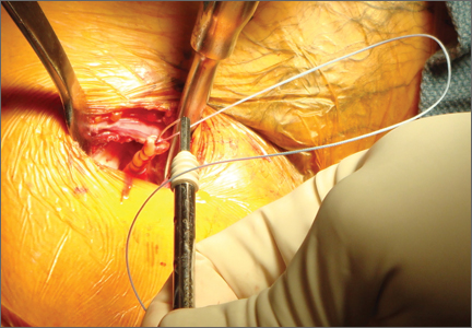
Navigating the Alphabet Soup of Labroligamentous Pathology of the Shoulder
The widespread use of eponyms and acronyms to describe labroligamentous findings in the shoulder has made interpretation of shoulder magnetic resonance imaging (MRI) reports challenging. We review and discuss the appearance of these lesions on shoulder MRI to help the orthopedic surgeon understand these entities as imaging findings.
Glenolabral articular disruption (GLAD) occurs secondary to impaction of the humeral head on the glenoid articular cartilage. There is a resultant defect in the glenoid articular cartilage, which extends to the glenoid labrum. A GLAD lesion is diagnosed only if the glenohumeral ligament and scapular periosteum remain intact1 (Figure 1).
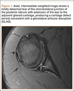
Complete detachment of the anteroinferior labrum with tearing of the anterior glenoid periosteum represents a Bankart lesion. Cartilaginous Bankart lesions are caused by an anterior glenohumeral dislocation with resultant avulsion of the anteroinferior labrum and disruption of the scapular periosteum because of acute traction on the anterior band of the inferior glenohumeral ligament (Figure 2). Anterior instability, caused by disruption of the anterior labroligamentous complex, results. Osseous Bankart lesions occur when the anterior displaced humeral head impacts the anterior inferior glenoid rim, causing a fracture (Figure 3). This loss of the glenoid articular surface area can result in glenohumeral instability. Posterior shoulder dislocations can result in corresponding findings in the posterior inferior glenoid labrum (reverse Bankart lesion) and anterior medial humeral head (reverse Hill-Sachs lesion) (Figure 2).
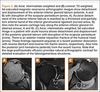
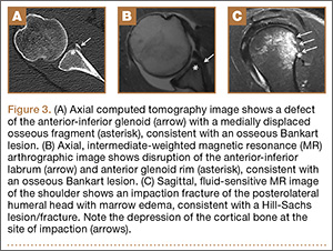
A variant of the Bankart lesion is the anterior labroligamentous periosteal sleeve avulsion (ALPSA). This refers to a medially displaced tear of the anterior labrum with intact periosteal stripping along the medial glenoid2with medial rotation and inferior displacement of the anterior inferior labrum along the scapular neck. An ALPSA lesion can heal via the intact periosteal blood supply. If not repaired, anterior instability will result because of malposition of the labrum, causing a patulous anterior capsule.3 When a corresponding lesion occurs in the posterior labrum because of a posterior dislocation, it is called a posterior labrocapsular periosteal sleeve avulsion (POLPSA) (Figure 4).
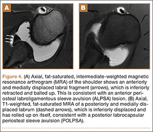
Another variant of the Bankart lesion is the Perthes lesion, which is a nondisplaced tear of the anteroinferior labrum with periosteal stripping. This differs from the ALPSA because the detached labrum and periosteum are held in anatomic position, possibly making the lesion difficult to detect on magnetic resonance arthrography (MRA).3 Obtaining images in the abduction external rotation (ABER) position exerts traction on the anterior inferior joint capsule and may make the Perthes lesion more conspicuous.4 When this occurs in the posterior labrum, it is called a reverse Perthes lesion (Figure 5).
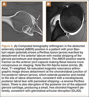
In a patient with anterior glenohumeral instability without a Bankart lesion, pathology of the anterior band of the inferior glenohumeral ligament (IGHL) at its humeral attachment must be suspected. Humeral avulsion of the IGHL (HAGL) or its variants can be overlooked on arthroscopy. HAGL is diagnosed on MRA when the normally U-shaped IGHL takes on a J-shape, and joint fluid extravasates across the torn humeral attachment (Figure 6). If there is an avulsed bony fragment from the medial humeral neck, the lesion is termed a bony HAGL (BHAGL). In addition to the findings of a HAGL, a BHAGL shows the osseous fragment and donor site on MRI. Since a BHAGL is a bony avulsion, it can even be suggested on radiography if a bony fragment is seen adjacent to the medial humeral neck.5 These lesions are highly associated with other shoulder injuries, particularly Hill-Sachs deformities and subscapularis tendon tears, and it is imperative, therefore, to search for additional injuries if a HAGL-type injury is seen.6
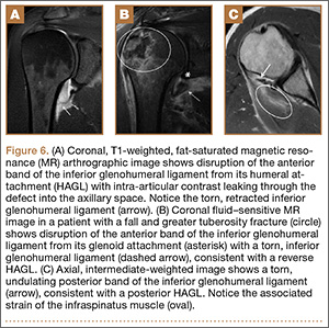
A more uncommon type of HAGL can occur in the setting of posterior capsulolabral injury. A posterior-band IGHL avulsion from the humerus (PHAGL) has similar imaging findings to a HAGL, except that it involves the posterior band of the IGHL. PHAGLs are usually not associated with an acute injury and are thought to be related to repetitive microtrauma, perhaps since the posterior band of the IGHL is the thinnest portion of the IGHL complex.7
A Kim lesion is an arthroscopic finding described in patients with posterior instability as a superficial defect at the undersurface of the posterior labrum and adjacent glenoid cartilage without detachment or extension to the chondrolabral junction.8 It is, by its nature, a concealed finding on routine MRI but can be more conspicuous in FADIR (flexed, adducted, internally rotated) positioning on MRA, which exerts traction on the posterior joint capsule, allowing intra-articular contrast to fill the tear (Figure 7).
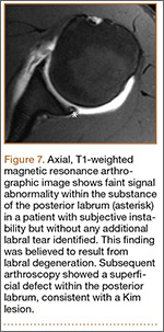
This list describes several of the most commonly encountered acronyms in shoulder MRI. A review of SLAP (superior labrum anterior to posterior) lesions was described in a previous article in the journal’s Imaging Series.9 A thorough understanding of these lesions is helpful in interpreting reports and determining the appropriate treatment for patients with shoulder injuries.
1. Sanders TG, Tirman PF, Linares R, Feller JF, Richardson R. The glenolabral articular disruption lesion: MR arthrography with arthroscopic correlation. AJR Am J Roentgenol. 1999;172(1):171-175.
2. Beltran J, Jbara M, Maimon R. Shoulder: labrum and bicipital tendon. Top Magn Reson Imaging. 2003;14(1):35-50.
3. Waldt S, Burkart A, Imhoff AB, Bruegel M, Rummeny EJ, Woertler K. Anterior shoulder instability: accuracy of MR arthrography in the classification of anteroinferior labroligamentous injuries. Radiology. 2005;237(2):578-583.
4. Schreinemachers SA, van der Hulst VP, Willems J, Bipat S, van der Woude H. Is a single direct MR arthrography series in ABER position as accurate in detecting anteroinferior labroligamentous lesions as conventional MR arthrography? Skeletal Radiol. 2009;38(7):675-683.
5. Bui-Mansfield LT, Taylor DC, Uhorchak JM, Tenuta JT. Humeral avulsions of the glenohumeral ligament: imaging features and a review of the literature. AJR Am J Roentgenol. 2002;179(3):649-655.
6. Magee T. Prevalence of HAGL lesions and associated abnormalities on shoulder MR examination. Skeletal Radiol. 2014;43(3):307-313.
7. Chung CB, Sorenson S, Dwek JR, Resnick D. Humeral avulsion of the posterior band of the inferior glenohumeral ligament: MR arthrography and clinical correlation in 17 patients. AJR Am J Roentgenol. 2004;183(2):355-359.
8. Kim SH, Ha KI, Yoo JC, Noh KC. Kim’s lesion: an incomplete and concealed avulsion of the posteroinferior labrum in posterior or multidirectional posteroinferior instability of the shoulder. Arthroscopy. 2004;20(7):712-720.
9. Grubin J, Maderazo A, Fitzpatrick D. Imaging evaluation of superior labral anteroposterior (SLAP) tears. Am J Orthop. 2015;44(10):476-477.
The widespread use of eponyms and acronyms to describe labroligamentous findings in the shoulder has made interpretation of shoulder magnetic resonance imaging (MRI) reports challenging. We review and discuss the appearance of these lesions on shoulder MRI to help the orthopedic surgeon understand these entities as imaging findings.
Glenolabral articular disruption (GLAD) occurs secondary to impaction of the humeral head on the glenoid articular cartilage. There is a resultant defect in the glenoid articular cartilage, which extends to the glenoid labrum. A GLAD lesion is diagnosed only if the glenohumeral ligament and scapular periosteum remain intact1 (Figure 1).
Complete detachment of the anteroinferior labrum with tearing of the anterior glenoid periosteum represents a Bankart lesion. Cartilaginous Bankart lesions are caused by an anterior glenohumeral dislocation with resultant avulsion of the anteroinferior labrum and disruption of the scapular periosteum because of acute traction on the anterior band of the inferior glenohumeral ligament (Figure 2). Anterior instability, caused by disruption of the anterior labroligamentous complex, results. Osseous Bankart lesions occur when the anterior displaced humeral head impacts the anterior inferior glenoid rim, causing a fracture (Figure 3). This loss of the glenoid articular surface area can result in glenohumeral instability. Posterior shoulder dislocations can result in corresponding findings in the posterior inferior glenoid labrum (reverse Bankart lesion) and anterior medial humeral head (reverse Hill-Sachs lesion) (Figure 2).
A variant of the Bankart lesion is the anterior labroligamentous periosteal sleeve avulsion (ALPSA). This refers to a medially displaced tear of the anterior labrum with intact periosteal stripping along the medial glenoid2with medial rotation and inferior displacement of the anterior inferior labrum along the scapular neck. An ALPSA lesion can heal via the intact periosteal blood supply. If not repaired, anterior instability will result because of malposition of the labrum, causing a patulous anterior capsule.3 When a corresponding lesion occurs in the posterior labrum because of a posterior dislocation, it is called a posterior labrocapsular periosteal sleeve avulsion (POLPSA) (Figure 4).
Another variant of the Bankart lesion is the Perthes lesion, which is a nondisplaced tear of the anteroinferior labrum with periosteal stripping. This differs from the ALPSA because the detached labrum and periosteum are held in anatomic position, possibly making the lesion difficult to detect on magnetic resonance arthrography (MRA).3 Obtaining images in the abduction external rotation (ABER) position exerts traction on the anterior inferior joint capsule and may make the Perthes lesion more conspicuous.4 When this occurs in the posterior labrum, it is called a reverse Perthes lesion (Figure 5).
In a patient with anterior glenohumeral instability without a Bankart lesion, pathology of the anterior band of the inferior glenohumeral ligament (IGHL) at its humeral attachment must be suspected. Humeral avulsion of the IGHL (HAGL) or its variants can be overlooked on arthroscopy. HAGL is diagnosed on MRA when the normally U-shaped IGHL takes on a J-shape, and joint fluid extravasates across the torn humeral attachment (Figure 6). If there is an avulsed bony fragment from the medial humeral neck, the lesion is termed a bony HAGL (BHAGL). In addition to the findings of a HAGL, a BHAGL shows the osseous fragment and donor site on MRI. Since a BHAGL is a bony avulsion, it can even be suggested on radiography if a bony fragment is seen adjacent to the medial humeral neck.5 These lesions are highly associated with other shoulder injuries, particularly Hill-Sachs deformities and subscapularis tendon tears, and it is imperative, therefore, to search for additional injuries if a HAGL-type injury is seen.6
A more uncommon type of HAGL can occur in the setting of posterior capsulolabral injury. A posterior-band IGHL avulsion from the humerus (PHAGL) has similar imaging findings to a HAGL, except that it involves the posterior band of the IGHL. PHAGLs are usually not associated with an acute injury and are thought to be related to repetitive microtrauma, perhaps since the posterior band of the IGHL is the thinnest portion of the IGHL complex.7
A Kim lesion is an arthroscopic finding described in patients with posterior instability as a superficial defect at the undersurface of the posterior labrum and adjacent glenoid cartilage without detachment or extension to the chondrolabral junction.8 It is, by its nature, a concealed finding on routine MRI but can be more conspicuous in FADIR (flexed, adducted, internally rotated) positioning on MRA, which exerts traction on the posterior joint capsule, allowing intra-articular contrast to fill the tear (Figure 7).
This list describes several of the most commonly encountered acronyms in shoulder MRI. A review of SLAP (superior labrum anterior to posterior) lesions was described in a previous article in the journal’s Imaging Series.9 A thorough understanding of these lesions is helpful in interpreting reports and determining the appropriate treatment for patients with shoulder injuries.
1. Sanders TG, Tirman PF, Linares R, Feller JF, Richardson R. The glenolabral articular disruption lesion: MR arthrography with arthroscopic correlation. AJR Am J Roentgenol. 1999;172(1):171-175.
2. Beltran J, Jbara M, Maimon R. Shoulder: labrum and bicipital tendon. Top Magn Reson Imaging. 2003;14(1):35-50.
3. Waldt S, Burkart A, Imhoff AB, Bruegel M, Rummeny EJ, Woertler K. Anterior shoulder instability: accuracy of MR arthrography in the classification of anteroinferior labroligamentous injuries. Radiology. 2005;237(2):578-583.
4. Schreinemachers SA, van der Hulst VP, Willems J, Bipat S, van der Woude H. Is a single direct MR arthrography series in ABER position as accurate in detecting anteroinferior labroligamentous lesions as conventional MR arthrography? Skeletal Radiol. 2009;38(7):675-683.
5. Bui-Mansfield LT, Taylor DC, Uhorchak JM, Tenuta JT. Humeral avulsions of the glenohumeral ligament: imaging features and a review of the literature. AJR Am J Roentgenol. 2002;179(3):649-655.
6. Magee T. Prevalence of HAGL lesions and associated abnormalities on shoulder MR examination. Skeletal Radiol. 2014;43(3):307-313.
7. Chung CB, Sorenson S, Dwek JR, Resnick D. Humeral avulsion of the posterior band of the inferior glenohumeral ligament: MR arthrography and clinical correlation in 17 patients. AJR Am J Roentgenol. 2004;183(2):355-359.
8. Kim SH, Ha KI, Yoo JC, Noh KC. Kim’s lesion: an incomplete and concealed avulsion of the posteroinferior labrum in posterior or multidirectional posteroinferior instability of the shoulder. Arthroscopy. 2004;20(7):712-720.
9. Grubin J, Maderazo A, Fitzpatrick D. Imaging evaluation of superior labral anteroposterior (SLAP) tears. Am J Orthop. 2015;44(10):476-477.
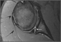
Lateral Ulnar Collateral Ligament Reconstruction: An Analysis of Ulnar Tunnel Locations
Posterolateral rotatory instability (PLRI) of the elbow is well recognized1 and is the most common type of chronic elbow instability. PLRI is often an end result of traumatic elbow dislocation.2 The “essential lesion” in patients with PLRI of the elbow is injury to the lateral ulnar collateral ligament (LUCL).1 However, more recent research has emphasized the importance of other ligaments in the lateral ligament complex (radial collateral and annular ligaments) in preventing PLRI.3-5 Nevertheless, when conservative treatment fails, the most commonly used surgical treatment involves LUCL reconstruction.1,6-11
Numerous techniques for LUCL reconstruction have been described.1,7-9,11-13 The chosen technique ideally restores normal anatomy. Therefore, the isometric point of origin at the lateral epicondyle and insertion at the supinator tubercle are important landmarks for creating tunnels that reproduce isometry, function, and normal anatomy. Most often, 2 tunnels are created in the ulna to secure the graft. It has been our experience that ulnar tunnel creation can affect the length of the bony bridge and the orientation of the graft.
We conducted a study to identify the precise proximal ulna tunnel location—anterior to posterior, with the distal tunnel at the supinator tubercle on the crest—that allows for the largest bony bridge and most geometrically favorable construct. We hypothesized that a most posteriorly placed proximal tunnel would increase bony bridge size and allow for a more isosceles graft configuration. An isosceles configuration with the humerus tunnel at the isometric location would allow for anterior and posterior bands of the same length with theoretically equal force distribution.
Methods
After obtaining institutional review board approval, we retrospectively reviewed the cases of 17 adults with elbow computed tomography (CT) scans for inclusion in this study. The scans were previously performed for diagnostic workup of several pathologies, including valgus instability, olecranon stress fracture, and valgus extension overload. The scan protocol involved 0.5-mm axial cuts with inclusion of the distal humerus through the proximal radius and ulna in the DICOM (Digital Imaging and Communications in Medicine) format. Exclusion criteria included poor CT quality, inadequate visualization of the entire supinator crest, and age under 18 years. Fifteen patients with adequate CT scans met the inclusion criteria. MIMICS (Materialise’s Interactive Medical Image Control System) software was used to convert scans into patient-specific 3-dimensional (3-D) computer models. (Use of this software to produce anatomically accurate models has been verified in shoulder14 and elbow15 models.) These models were uploaded into Magics rapid prototyping software (Materialise) and manipulated for simulated tunnel drilling by precise bone subtraction methods. This software was used to define an ulnar Cartesian coordinate system with anatomical landmarks as reference points in order to standardize the position of each model (Figure 1).16 The y-axis was defined by the longitudinal axis of the ulna, and the x-axis was the transepicondylar axis, defined as the perpendicular line connecting the y-axis with the supinator crest. The z-axis was then established as the line perpendicular to the x- and y-axes—yielding a 3-D coordinate system that allowed us to manipulate the models in standardized fashion, maintaining the exact positions of the ulna while making measurements.
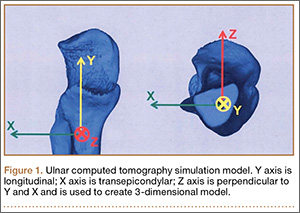
Surgical simulations were performed in the rapid prototyping software by creating a cylinder and placing it at the desired location of each tunnel. Cylinder diameter was 4 mm, matching the diameter of the drill we use to create each tunnel in our practice. The cylinder was inserted into the bone, perpendicular to the surface of the ulna at the point of insertion, so the cylinder’s deepest point entered the medullary canal of the ulna. Using a Boolean operation in the rapid prototyping software, we subtracted cylinder from bone to create a tunnel (Figure 2).15
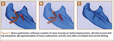
In a previous study,17 we determined that the radial head junction is reproducibly about 15 mm proximal to the distinct supinator tubercle, which may be absent or not readily appreciated in up to 50% of cases. Therefore, proximal ulnar tunnels were placed 0, 5, and 10 mm posterior to the supinator crest at the radial head junction. Distal tunnels were placed 15 mm anterior to the radial head junction on the supinator crest (Figure 2). The bony bridges created by these tunnels were measured, as was the distance between the distal tunnel and the supinator tubercle.
Ideal graft configuration was described as an isosceles triangle with ulna tunnels perpendicular to the humeral tunnel (Figure 3).11 Location of the humeral origin in the sagittal plane was determined by finding the isometric point of the lateral humerus using only bony landmarks. Similar techniques have been used to find the isometric point on the medial epicondyle for medial ulnar collateral ligament reconstruction.15,18 With a circle fit into the trochlear notch of the ulna, the isometric point can be determined by the center of the circle. This point was then superimposed on the humerus to identify the starting point (Figure 4). In our simulation, we measured the isosceles configuration by drawing a line between the proximal and distal tunnels, and then another line connecting the bisecting point of the first line with the isometric point on the humerus from which the graft would originate. The angle between the 2 lines was measured; if isosceles, the angle was 90° (Figure 5). Length of the more proximal limb of the graft and the more distal limb of the graft was determined by measuring the distance from the isometric point to the proximal and distal tunnels, respectively (Figure 6).

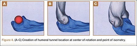
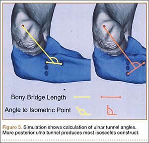
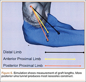
One-way analysis of variance was used to compare all the tunnels’ bony bridge sizes, graft lengths, and angles to the isometric point. For all comparisons, statistical significance was set at P < .05. As no other studies have compared bony bridges by varying tunnel creation parameters, and as the present study is observational and not comparative, no power analysis was performed.
Results
Bony bridges were significantly longer, and angles more perpendicular, with increasing distance from the proximal tunnel to the supinator crest (Table 1, Figure 5, Figure 7). The bony bridge 0 mm posterior to the supinator crest yielded a mean (SE) bony bridge length of 11.0 (0.2) mm. This proximal tunnel also yielded the smallest mean (SE) perpendicular angle to the isometric point, 131.2° (1.9°). The tunnel most posterior to the supinator crest yielded the longest mean (SE) bony bridge, 13.7 (0.2) mm, and the largest mean (SE) degree of perpendicularity, 95.8° (1.4°). The differences between all tunnels’ bony bridges and isometric angles were statistically significant (P < .00001). The difference between the more distal limb and the more proximal limb of the graft was smallest in the more posteriorly placed proximal tunnel (Table 2, Figure 8). In fact, there was no statistical difference between the proximal and distal limbs of the graft when the proximal tunnel was placed 10 mm posterior to the supinator crest: Mean (SE) was 9.4 (0.5) mm at 0 mm (P < .00001) and 1.1 (0.6) mm at 10 mm (P = .24).
![]()
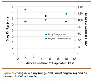
![]()
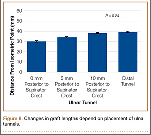
Discussion
PLRI of the elbow is best initially managed nonoperatively. However, when nonoperative management fails, the LUCL is often surgically reconstructed. Reconstruction methods vary by fixation method, graft choice, and bone tunnels.1,7-9,11-13 In 1991, O’Driscoll and colleagues1 described a “yoke” technique for LUCL reconstruction. Since then, the docking technique7 and other techniques have been developed. All these techniques emphasize maximizing anatomical precision and isometry with careful placement of tunnels or fixation devices. The humeral fixation site, at the anterior inferior aspect of the lateral epicondyle at the point of isometry, can be accessed relatively reproducibly. By contrast, the ulnar points of fixation are more variable, because of increased bone stock and overlying soft-tissue and bony anatomy.
Among the challenges in determining the points of ulnar fixation is the bony anatomy that is often used for landmarks. In the literature, the supinator crest or the supintor tubercle is the landmark for placing the distal tunnel.1,7-9,11-13 This is a problem for 2 reasons. First, the supintor crest, a longitudinal structure on the lateral aspect of the ulna, originates from the radial head junction and extends tens of millimeters distally; further specification is needed to guide these ulnar tunnels. The second reason is that use of the supinator tubercle, a prominence on the supinator crest, adds specificity to the location of the ulnar tunnels. During surgery, however, the supinator tubercle may not be a reliable, independently prominent structure; instead, it may be indistinguishable from the supinator crest, on which it rests. One study determined that only about 50% of computer models of patient ulnas had a distinct prominence that could be classified as the supinator tubercle.17 The percentage presumably is lower during surgery, with limited exposure and overlying soft tissues.
In a study of patients with a prominent tubercle, mean (SE) distance from radial head junction to tubercle was 15 (2) mm.17 This finding led us to use the radial head junction as the primary bony landmark in determining the location of the proximal tunnel and placing the distal tunnel 15 mm distally—achieving the same fixation described in the literature but using more distinct landmarks. Our study thus provided a reliable, verified approach to locating the ulnar tunnels in the proximal-distal axis.
We also explored the anterior-posterior orientation of the proximal ulnar tunnel. The 2 primary considerations surrounding the varied proximal tunnel placements were the bony bridge formed between the proximal and distal tunnels and the perpendicularity of the triangle formed by the fixation points. Maximizing the bony bridge is obviously ideal in securing and preventing fixation blowout. Achieving an isoceles reconstruction has been reported in the literature on the various fixation techniques for LUCL reconstruction.11 Although the biomechanical advantage of this fixation type is not fully clear, we assume the construct produces graft stands of equal length, tension, and stability. In addition, the larger footprint created by an isoceles reconstructed ligament increases the stability of the radial head.
Results of the present study showed that the more posterior the proximal ulnar tunnel, the longer the bony bridge and the more isoceles the reconstruction. The difference in bony bridge distance from the most anterior to the most posterior tunnel was about 2 mm, or 18%. For every 1 mm of posteriorization, the bony bridge was 0.2 mm longer. The line from the isometric point of humeral fixation bisecting the proximal and distal tunnels was also more perpendicular with the most posterior tunnel, by about 40°. The resulting proximal and distal limbs of the reconstruction were equal in length, as demonstrated by the smaller difference between the limbs. We assume this isoceles reconstruction more likely applies uniform restraint on the radial head. Thus, an effort should be made to posteriorize the proximal ulnar tunnel during reconstruction.
The study was limited by the number of patient-specific elbow models used. However, given the statistical consistency of measurements, sample size was sufficient. Another limitation, inherent to the model, was that only bony anatomy was incorporated. However, the overlying muscles, tendons, and ligaments can significantly alter tunnel placement, and this study provided other means and cues using more reliable landmarks to adequately place the tunnels. As this was a simulation study, we cannot confirm whether these results would make a difference clinically. The strengths of this study include development and verification of reliable landmarks that can be used to guide ulnar tunnel locations during LUCL reconstruction; these landmarks have been used for medial ulnar collateral ligament reconstruction.15 Other strengths include precise and accurate placement of tunnels and measurement of resulting bony bridges—accomplished independently and without compromising specimen quality.
Conclusion
We recommend drilling the proximal ulnar tunnel posterior to the supinator crest at the level of the radial head junction. A reasonable goal is 10 mm posterior to the crest, though the overlying soft tissue must be considered, and care should be taken to aim the drill anteriorly, toward the ulna’s intramedullary canal, to avoid posterior cortical breach. The distal ulnar tunnel should be drilled just posterior to the supinator crest, 15 mm distal to the radial head junction.
1. O’Driscoll SW, Bell DF, Morrey BF. Posterolateral rotatory instability of the elbow. J Bone Joint Surg Am. 1991;73(3):440-446.
2. O’Driscoll SW. Classification and evaluation of recurrent instability of the elbow. Clin Orthop Relat Res. 2000;370:34-43.
3. Takigawa N, Ryu J, Kish VL, Kinoshita M, Abe M. Functional anatomy of the lateral collateral ligament complex of the elbow: morphology and strain. J Hand Surg Br. 2005;30(2):143-147.
4. McAdams TR, Masters GW, Srivastava S. The effect of arthroscopic sectioning of the lateral ligament complex of the elbow on posterolateral rotatory stability. J Shoulder Elbow Surg. 2005;14(3):298-301.
5. Dunning CE, Zarzour ZD, Patterson SD, Johnson JA, King GJ. Ligamentous stabilizers against posterolateral rotatory instability of the elbow. J Bone Joint Surg Am. 2001;83(12):1823-1828.
6. Eygendaal D. Ligamentous reconstruction around the elbow using triceps tendon. Acta Orthop Scand. 2004;75(5):516-523.
7. Jones KJ, Dodson CC, Osbahr DC, et al. The docking technique for lateral ulnar collateral ligament reconstruction: surgical technique and clinical outcomes. J Shoulder Elbow Surg. 2012;21(3):389-395.
8. Lee BP, Teo LH. Surgical reconstruction for posterolateral rotatory instability of the elbow. J Shoulder Elbow Surg. 2003;12(5):476-479.
9. Lin KY, Shen PH, Lee CH, Pan RY, Lin LC, Shen HC. Functional outcomes of surgical reconstruction for posterolateral rotatory instability of the elbow. Injury. 2012;43(10):1657-1661.
10. Olsen BS, Søjbjerg JO. The treatment of recurrent posterolateral instability of the elbow. J Bone Joint Surg Br. 2003;85(3):342-346.
11. Sanchez-Sotelo J, Morrey BF, O’Driscoll SW. Ligamentous repair and reconstruction for posterolateral rotatory instability of the elbow. J Bone Joint Surg Br. 2005;87(1):54-61.
12. Savoie FH 3rd, Field LD, Gurley DJ. Arthroscopic and open radial ulnohumeral ligament reconstruction for posterolateral rotatory instability of the elbow. Hand Clin. 2009;25(3):323-329.
13. Savoie FH 3rd, O’Brien MJ, Field LD, Gurley DJ. Arthroscopic and open radial ulnohumeral ligament reconstruction for posterolateral rotatory instability of the elbow. Clin Sports Med. 2010;29(4):611-618.
14. Bryce CD, Pennypacker JL, Kulkarni N, et al. Validation of three-dimensional models of in situ scapulae. J Shoulder Elbow Surg. 2008;17(5):825-832.
15. Byram IR, Khanna K, Gardner TR, Ahmad CS. Characterizing bone tunnel placement in medial ulnar collateral ligament reconstruction using patient-specific 3-dimensional computed tomography modeling. Am J Sports Med. 2013;41(4):894-902.
16. Shiba R, Sorbie C, Siu DW, Bryant JT, Cooke TD, Wevers HW. Geometry of the humeroulnar joint. J Orthop Res. 1988;6(6):897-906.
17. Anakwenze OA, Khanna K, Levine WN, Ahmad CS. Characterization of the supinator tubercle for lateral ulnar collateral ligament reconstruction. Orthop J Sports Med. 2014;2(4):2325967114530969. doi:10.1177/2325967114530969.
18. Sasashige Y, Ochi M, Ikuta Y. Optimal attachment site for reconstruction of the ulnar collateral ligament. A cadaver study. Arch Orthop Trauma Surg. 1994;113(5):265-270.
Posterolateral rotatory instability (PLRI) of the elbow is well recognized1 and is the most common type of chronic elbow instability. PLRI is often an end result of traumatic elbow dislocation.2 The “essential lesion” in patients with PLRI of the elbow is injury to the lateral ulnar collateral ligament (LUCL).1 However, more recent research has emphasized the importance of other ligaments in the lateral ligament complex (radial collateral and annular ligaments) in preventing PLRI.3-5 Nevertheless, when conservative treatment fails, the most commonly used surgical treatment involves LUCL reconstruction.1,6-11
Numerous techniques for LUCL reconstruction have been described.1,7-9,11-13 The chosen technique ideally restores normal anatomy. Therefore, the isometric point of origin at the lateral epicondyle and insertion at the supinator tubercle are important landmarks for creating tunnels that reproduce isometry, function, and normal anatomy. Most often, 2 tunnels are created in the ulna to secure the graft. It has been our experience that ulnar tunnel creation can affect the length of the bony bridge and the orientation of the graft.
We conducted a study to identify the precise proximal ulna tunnel location—anterior to posterior, with the distal tunnel at the supinator tubercle on the crest—that allows for the largest bony bridge and most geometrically favorable construct. We hypothesized that a most posteriorly placed proximal tunnel would increase bony bridge size and allow for a more isosceles graft configuration. An isosceles configuration with the humerus tunnel at the isometric location would allow for anterior and posterior bands of the same length with theoretically equal force distribution.
Methods
After obtaining institutional review board approval, we retrospectively reviewed the cases of 17 adults with elbow computed tomography (CT) scans for inclusion in this study. The scans were previously performed for diagnostic workup of several pathologies, including valgus instability, olecranon stress fracture, and valgus extension overload. The scan protocol involved 0.5-mm axial cuts with inclusion of the distal humerus through the proximal radius and ulna in the DICOM (Digital Imaging and Communications in Medicine) format. Exclusion criteria included poor CT quality, inadequate visualization of the entire supinator crest, and age under 18 years. Fifteen patients with adequate CT scans met the inclusion criteria. MIMICS (Materialise’s Interactive Medical Image Control System) software was used to convert scans into patient-specific 3-dimensional (3-D) computer models. (Use of this software to produce anatomically accurate models has been verified in shoulder14 and elbow15 models.) These models were uploaded into Magics rapid prototyping software (Materialise) and manipulated for simulated tunnel drilling by precise bone subtraction methods. This software was used to define an ulnar Cartesian coordinate system with anatomical landmarks as reference points in order to standardize the position of each model (Figure 1).16 The y-axis was defined by the longitudinal axis of the ulna, and the x-axis was the transepicondylar axis, defined as the perpendicular line connecting the y-axis with the supinator crest. The z-axis was then established as the line perpendicular to the x- and y-axes—yielding a 3-D coordinate system that allowed us to manipulate the models in standardized fashion, maintaining the exact positions of the ulna while making measurements.
Surgical simulations were performed in the rapid prototyping software by creating a cylinder and placing it at the desired location of each tunnel. Cylinder diameter was 4 mm, matching the diameter of the drill we use to create each tunnel in our practice. The cylinder was inserted into the bone, perpendicular to the surface of the ulna at the point of insertion, so the cylinder’s deepest point entered the medullary canal of the ulna. Using a Boolean operation in the rapid prototyping software, we subtracted cylinder from bone to create a tunnel (Figure 2).15
In a previous study,17 we determined that the radial head junction is reproducibly about 15 mm proximal to the distinct supinator tubercle, which may be absent or not readily appreciated in up to 50% of cases. Therefore, proximal ulnar tunnels were placed 0, 5, and 10 mm posterior to the supinator crest at the radial head junction. Distal tunnels were placed 15 mm anterior to the radial head junction on the supinator crest (Figure 2). The bony bridges created by these tunnels were measured, as was the distance between the distal tunnel and the supinator tubercle.
Ideal graft configuration was described as an isosceles triangle with ulna tunnels perpendicular to the humeral tunnel (Figure 3).11 Location of the humeral origin in the sagittal plane was determined by finding the isometric point of the lateral humerus using only bony landmarks. Similar techniques have been used to find the isometric point on the medial epicondyle for medial ulnar collateral ligament reconstruction.15,18 With a circle fit into the trochlear notch of the ulna, the isometric point can be determined by the center of the circle. This point was then superimposed on the humerus to identify the starting point (Figure 4). In our simulation, we measured the isosceles configuration by drawing a line between the proximal and distal tunnels, and then another line connecting the bisecting point of the first line with the isometric point on the humerus from which the graft would originate. The angle between the 2 lines was measured; if isosceles, the angle was 90° (Figure 5). Length of the more proximal limb of the graft and the more distal limb of the graft was determined by measuring the distance from the isometric point to the proximal and distal tunnels, respectively (Figure 6).
One-way analysis of variance was used to compare all the tunnels’ bony bridge sizes, graft lengths, and angles to the isometric point. For all comparisons, statistical significance was set at P < .05. As no other studies have compared bony bridges by varying tunnel creation parameters, and as the present study is observational and not comparative, no power analysis was performed.
Results
Bony bridges were significantly longer, and angles more perpendicular, with increasing distance from the proximal tunnel to the supinator crest (Table 1, Figure 5, Figure 7). The bony bridge 0 mm posterior to the supinator crest yielded a mean (SE) bony bridge length of 11.0 (0.2) mm. This proximal tunnel also yielded the smallest mean (SE) perpendicular angle to the isometric point, 131.2° (1.9°). The tunnel most posterior to the supinator crest yielded the longest mean (SE) bony bridge, 13.7 (0.2) mm, and the largest mean (SE) degree of perpendicularity, 95.8° (1.4°). The differences between all tunnels’ bony bridges and isometric angles were statistically significant (P < .00001). The difference between the more distal limb and the more proximal limb of the graft was smallest in the more posteriorly placed proximal tunnel (Table 2, Figure 8). In fact, there was no statistical difference between the proximal and distal limbs of the graft when the proximal tunnel was placed 10 mm posterior to the supinator crest: Mean (SE) was 9.4 (0.5) mm at 0 mm (P < .00001) and 1.1 (0.6) mm at 10 mm (P = .24).
![]()
![]()
Discussion
PLRI of the elbow is best initially managed nonoperatively. However, when nonoperative management fails, the LUCL is often surgically reconstructed. Reconstruction methods vary by fixation method, graft choice, and bone tunnels.1,7-9,11-13 In 1991, O’Driscoll and colleagues1 described a “yoke” technique for LUCL reconstruction. Since then, the docking technique7 and other techniques have been developed. All these techniques emphasize maximizing anatomical precision and isometry with careful placement of tunnels or fixation devices. The humeral fixation site, at the anterior inferior aspect of the lateral epicondyle at the point of isometry, can be accessed relatively reproducibly. By contrast, the ulnar points of fixation are more variable, because of increased bone stock and overlying soft-tissue and bony anatomy.
Among the challenges in determining the points of ulnar fixation is the bony anatomy that is often used for landmarks. In the literature, the supinator crest or the supintor tubercle is the landmark for placing the distal tunnel.1,7-9,11-13 This is a problem for 2 reasons. First, the supintor crest, a longitudinal structure on the lateral aspect of the ulna, originates from the radial head junction and extends tens of millimeters distally; further specification is needed to guide these ulnar tunnels. The second reason is that use of the supinator tubercle, a prominence on the supinator crest, adds specificity to the location of the ulnar tunnels. During surgery, however, the supinator tubercle may not be a reliable, independently prominent structure; instead, it may be indistinguishable from the supinator crest, on which it rests. One study determined that only about 50% of computer models of patient ulnas had a distinct prominence that could be classified as the supinator tubercle.17 The percentage presumably is lower during surgery, with limited exposure and overlying soft tissues.
In a study of patients with a prominent tubercle, mean (SE) distance from radial head junction to tubercle was 15 (2) mm.17 This finding led us to use the radial head junction as the primary bony landmark in determining the location of the proximal tunnel and placing the distal tunnel 15 mm distally—achieving the same fixation described in the literature but using more distinct landmarks. Our study thus provided a reliable, verified approach to locating the ulnar tunnels in the proximal-distal axis.
We also explored the anterior-posterior orientation of the proximal ulnar tunnel. The 2 primary considerations surrounding the varied proximal tunnel placements were the bony bridge formed between the proximal and distal tunnels and the perpendicularity of the triangle formed by the fixation points. Maximizing the bony bridge is obviously ideal in securing and preventing fixation blowout. Achieving an isoceles reconstruction has been reported in the literature on the various fixation techniques for LUCL reconstruction.11 Although the biomechanical advantage of this fixation type is not fully clear, we assume the construct produces graft stands of equal length, tension, and stability. In addition, the larger footprint created by an isoceles reconstructed ligament increases the stability of the radial head.
Results of the present study showed that the more posterior the proximal ulnar tunnel, the longer the bony bridge and the more isoceles the reconstruction. The difference in bony bridge distance from the most anterior to the most posterior tunnel was about 2 mm, or 18%. For every 1 mm of posteriorization, the bony bridge was 0.2 mm longer. The line from the isometric point of humeral fixation bisecting the proximal and distal tunnels was also more perpendicular with the most posterior tunnel, by about 40°. The resulting proximal and distal limbs of the reconstruction were equal in length, as demonstrated by the smaller difference between the limbs. We assume this isoceles reconstruction more likely applies uniform restraint on the radial head. Thus, an effort should be made to posteriorize the proximal ulnar tunnel during reconstruction.
The study was limited by the number of patient-specific elbow models used. However, given the statistical consistency of measurements, sample size was sufficient. Another limitation, inherent to the model, was that only bony anatomy was incorporated. However, the overlying muscles, tendons, and ligaments can significantly alter tunnel placement, and this study provided other means and cues using more reliable landmarks to adequately place the tunnels. As this was a simulation study, we cannot confirm whether these results would make a difference clinically. The strengths of this study include development and verification of reliable landmarks that can be used to guide ulnar tunnel locations during LUCL reconstruction; these landmarks have been used for medial ulnar collateral ligament reconstruction.15 Other strengths include precise and accurate placement of tunnels and measurement of resulting bony bridges—accomplished independently and without compromising specimen quality.
Conclusion
We recommend drilling the proximal ulnar tunnel posterior to the supinator crest at the level of the radial head junction. A reasonable goal is 10 mm posterior to the crest, though the overlying soft tissue must be considered, and care should be taken to aim the drill anteriorly, toward the ulna’s intramedullary canal, to avoid posterior cortical breach. The distal ulnar tunnel should be drilled just posterior to the supinator crest, 15 mm distal to the radial head junction.
1. O’Driscoll SW, Bell DF, Morrey BF. Posterolateral rotatory instability of the elbow. J Bone Joint Surg Am. 1991;73(3):440-446.
2. O’Driscoll SW. Classification and evaluation of recurrent instability of the elbow. Clin Orthop Relat Res. 2000;370:34-43.
3. Takigawa N, Ryu J, Kish VL, Kinoshita M, Abe M. Functional anatomy of the lateral collateral ligament complex of the elbow: morphology and strain. J Hand Surg Br. 2005;30(2):143-147.
4. McAdams TR, Masters GW, Srivastava S. The effect of arthroscopic sectioning of the lateral ligament complex of the elbow on posterolateral rotatory stability. J Shoulder Elbow Surg. 2005;14(3):298-301.
5. Dunning CE, Zarzour ZD, Patterson SD, Johnson JA, King GJ. Ligamentous stabilizers against posterolateral rotatory instability of the elbow. J Bone Joint Surg Am. 2001;83(12):1823-1828.
6. Eygendaal D. Ligamentous reconstruction around the elbow using triceps tendon. Acta Orthop Scand. 2004;75(5):516-523.
7. Jones KJ, Dodson CC, Osbahr DC, et al. The docking technique for lateral ulnar collateral ligament reconstruction: surgical technique and clinical outcomes. J Shoulder Elbow Surg. 2012;21(3):389-395.
8. Lee BP, Teo LH. Surgical reconstruction for posterolateral rotatory instability of the elbow. J Shoulder Elbow Surg. 2003;12(5):476-479.
9. Lin KY, Shen PH, Lee CH, Pan RY, Lin LC, Shen HC. Functional outcomes of surgical reconstruction for posterolateral rotatory instability of the elbow. Injury. 2012;43(10):1657-1661.
10. Olsen BS, Søjbjerg JO. The treatment of recurrent posterolateral instability of the elbow. J Bone Joint Surg Br. 2003;85(3):342-346.
11. Sanchez-Sotelo J, Morrey BF, O’Driscoll SW. Ligamentous repair and reconstruction for posterolateral rotatory instability of the elbow. J Bone Joint Surg Br. 2005;87(1):54-61.
12. Savoie FH 3rd, Field LD, Gurley DJ. Arthroscopic and open radial ulnohumeral ligament reconstruction for posterolateral rotatory instability of the elbow. Hand Clin. 2009;25(3):323-329.
13. Savoie FH 3rd, O’Brien MJ, Field LD, Gurley DJ. Arthroscopic and open radial ulnohumeral ligament reconstruction for posterolateral rotatory instability of the elbow. Clin Sports Med. 2010;29(4):611-618.
14. Bryce CD, Pennypacker JL, Kulkarni N, et al. Validation of three-dimensional models of in situ scapulae. J Shoulder Elbow Surg. 2008;17(5):825-832.
15. Byram IR, Khanna K, Gardner TR, Ahmad CS. Characterizing bone tunnel placement in medial ulnar collateral ligament reconstruction using patient-specific 3-dimensional computed tomography modeling. Am J Sports Med. 2013;41(4):894-902.
16. Shiba R, Sorbie C, Siu DW, Bryant JT, Cooke TD, Wevers HW. Geometry of the humeroulnar joint. J Orthop Res. 1988;6(6):897-906.
17. Anakwenze OA, Khanna K, Levine WN, Ahmad CS. Characterization of the supinator tubercle for lateral ulnar collateral ligament reconstruction. Orthop J Sports Med. 2014;2(4):2325967114530969. doi:10.1177/2325967114530969.
18. Sasashige Y, Ochi M, Ikuta Y. Optimal attachment site for reconstruction of the ulnar collateral ligament. A cadaver study. Arch Orthop Trauma Surg. 1994;113(5):265-270.
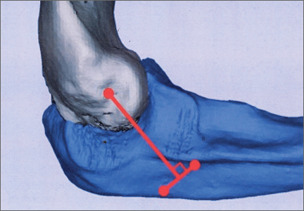
Reconstructive Shelf Arthroplasty as a Salvage Procedure for Complex Fifth Tarsometatarsal Joint Complex Injuries: A Case Review and Discussion
Fractures of the cuboid bone are uncommon, with an annual incidence of approximately 1.8 per 100,000.1 This is largely attributed to the inherent stability provided by its anatomy and position in the foot’s lateral column, where it functions as a link between the lateral column and transverse plantar arch.2 Regarding its anatomy, the cuboid is a pyramidal-shaped bone with 6 bony surfaces that provide tremendous stability—3 of these are articular, 3 nonarticular.
Although the cuboid bone is susceptible to low-energy avulsion injuries, injuries that occur in the setting of high-energy trauma are most concerning, as they often occur concurrently with other midfoot fractures and dislocations. These less common crush injuries are associated with comminution, articular disruption, and shortening of the lateral column.3-5 Avulsion injuries occur via a twisting mechanism, while the more complex nutcracker fracture evolves via longitudinal compression of the lateral column, with the foot in a position of forced plantarflexion.6 Other comminuted fractures occur from direct impact on the lateral aspect of the foot.
Management of cuboid fractures varies according to etiology, fracture displacement, and articular involvement. Conservative management is reserved solely for stable, nondisplaced fractures.7 Unstable fracture-dislocations and those with associated lateral column shortening necessitate operative treatment, which attempts to restore anatomy, stability, and length of the foot’s lateral column.7-9 However, with the exception of open injuries, fractures tenting the skin, and injuries with concomitant compartment syndrome, the high-energy nature of cuboid fractures often precludes early surgical intervention, as the foot’s soft-tissue envelope is too compromised. For this reason, operative intervention is often performed on a delayed basis only after recovery of the soft tissue.
In this case report and literature review, we describe a reconstructive shelf arthroplasty of the fifth tarsometatarsal (TMT) joint as a primary intervention for crush-type cuboid fractures with associated joint subsidence and lateral column shortening. The shelf arthroplasty, which was first credited to Konig in 1891, has historically been described as a remodeling operation using bone graft wedges for the treatment of nonconcentric acetabular dysplasia.10 Although bone grafting is recognized as an effective means of addressing osseous voids in the setting of comminuted cuboid fractures, its specific application in the form of a shelf arthroplasty has not been described.11 The patient provided written informed consent for print and electronic publication of this case report.
Case Report
An otherwise healthy 45-year-old woman presented to our institution’s emergency department (ED) complaining of right foot pain after a motor vehicle accident. She was the restrained driver in a head-on collision. Primary survey revealed a swollen, ecchymotic, and tender right foot. Radiographs demonstrated fractures of her first, second, third, and fourth metatarsals, and a comminuted cuboid fracture with lateral column shortening and disruption of the fifth TMT joint (Figure 1).
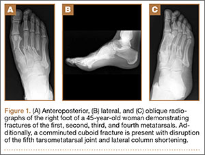
Due to swelling, initial management consisted of soft-tissue management through the use of a well-padded splint. As this was her only injury, she was instructed to remain non-weight-bearing, ambulate with crutches, and return to our outpatient office for close follow-up. The need for delayed surgical intervention of her multiple foot injuries, due to her compromised soft-tissue envelope, was discussed prior to discharge.
Surgical intervention was performed 15 days after the injury, when the soft-tissue swelling had dissipated. The surgical plan included fixation of the multiple metatarsal fractures and lateral column reconstruction and stabilization. With regard to the lateral column, we obtained patient consent for several possible procedures, including fifth TMT joint closed reduction and percutaneous pinning, open reduction and internal fixation (ORIF), and TMT joint reconstruction with iliac crest bone graft (ICBG).
The metatarsals were addressed first via a dorsomedial incision, using a 5-hole 2.7-mm Limited Contact Dynamic Compression Plate (Synthes) to stabilize the first metatarsal and 2.0-mm Kirschner wires (K-wires) to maintain the length and alignment of the second, third, and fourth metatarsals (Figure 2). Closed reduction and percutaneous pinning of the fifth metatarsal was then attempted but abandoned because of persistent instability and subsidence of the cuboid in the proximal and plantar direction. ORIF was then attempted through a dorsolateral incision extending from just distal to the sinus tarsi to the base of the fourth metatarsal. However, the lateral cuboid was too comminuted to accommodate any fixation and prevent fifth TMT joint subluxation and lateral column shortening.
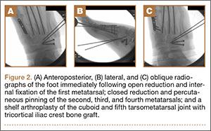
Autograft reconstruction of the lateral column was therefore performed, using radiographs of the patient’s uninjured, contralateral foot as a template for our lateral column shelf arthroplasty (Figure 3). Based on this template, the length and alignment of the lateral column were provisionally maintained with two 2.0-mm K-wires placed between the fifth metatarsal and intact cuboid (Figure 4). Tricortical ICBG was then harvested through an anterior approach to the iliac crest and contoured accordingly to fill the osseous void. To facilitate graft incorporation, comminuted fragments of cuboid bone were removed, with the remaining bone decorticated. The graft was then fixed to the remaining cuboid with two 4.0-mm partially threaded cannulated screws (Synthes; Figures 2, 4). This construct restored the length of the lateral column and effectively buttressed the fifth TMT joint, preventing subsidence and dislocation of the TMT joint.
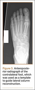
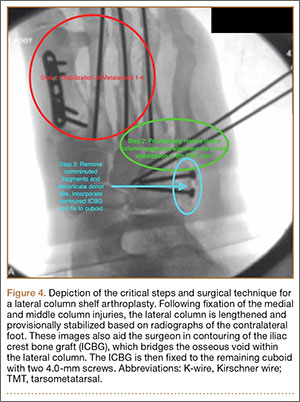
After a 2-day postoperative course in the hospital, the patient was discharged. She remained non-weight-bearing in a splint with Robert Jones cotton bandage. At her 2-week postoperative visit, all hardware was intact and there was no evidence of infection. Her sutures were removed and she was placed in a new splint. At the patient’s 5-week postoperative visit, all K-wires were removed. At this time she remained non-weight-bearing but was transitioned into a controlled ankle movement (CAM) boot and was allowed to begin active and passive ankle exercises. At her 10-week follow-up, radiographs revealed appropriate interval healing and callus formation. The patient began weight-bearing as tolerated in the CAM boot at that time. At 12 weeks, she was transitioned into a hard-soled shoe for comfort and was allowed to ambulate in the footwear of her choice as tolerated. Her activity levels were slowly advanced, and, at her 12-month follow-up, the patient had returned to playing tennis in her recreational league with no residual sequelae (Figure 5).
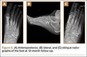
Discussion
Although rare, cuboid fractures are critical to identify and can result in significant disability, as they are frequently associated with additional foot trauma, as demonstrated in this case.1-4When isolated cuboid fractures are present, further imaging must be performed, including additional radiographic views and computed tomography, to search for other injuries, such as TMT joint complex disruption.
Only those cuboid fractures that are low-energy, stable, or nondisplaced can be effectively managed conservatively.12In the presence of instability, articular incongruity, or lateral column shortening, operative intervention is warranted. Arthritic degeneration, pain, and deformity result from residual incongruity at the calcaneocuboid or TMT joints, or when lateral column length is not restored.4-6,13 The latter leads to forefoot abduction and lateral subluxation of the lesser metatarsals, with ensuing posttraumatic pes planus or planovalgus deformity, which often necessitates secondary reconstructive procedures or arthrodesis.14,15 Stable reduction and restoration of lateral column length can be challenging, particularly in the setting of comminution and bone loss. Common methods of treatment involve lifting the dorsolateral cortex of the cuboid and buttressing the impacted articular surface with bone graft or bone graft substitutes. Fixation can be achieved with K-wires, small fragment plates and screws, and distraction external fixation.11 The latter is a particularly beneficial technique, as it can be used independent of or in conjunction with ORIF.
In a study by Weber and Locher,11 the short-term to midterm results of cuboid ORIF were assessed in 12 patients. Results were found to be good with respect to restoration of length, joint reconstruction, and overall return to function.11 Admittedly, these authors at times employed a similar but conceptually different approach to our patient. In their 7 patients with severe comminution and lateral column shortening, corticocancellous ICBG was used. However, Weber and Locher11did not describe this as a shelf arthroplasty, but instead as an adjunct to primary ORIF.
In our case, the tricortical ICBG shelf arthroplasty was used as it is in the hip, as a salvage procedure. Although little is known about outcomes following shelf arthroplasty for lateral column reconstruction in the foot, a 50% failure rate has been observed in the hip.16 As such, our preference was to perform an anatomic ORIF of the cuboid and lateral column, with the shelf arthroplasty only indicated if we were unable to achieve this. We believe that the need for tricortical ICBG in the treatment of cuboid fractures is indicative of a more severe injury and that it is a less optimal and more technically demanding intervention compared with primary ORIF. Furthermore, in other studies devoted to the treatment of cuboid fractures, patients requiring reconstruction with structural graft are not included in primary ORIF cohorts.17
As in the hip, suboptimal outcomes may occur when shelf arthroplasty is performed in the foot. There are additional considerations unique to the foot that surgeons must also contemplate when considering shelf arthroplasty. As demonstrated in the literature for adult-acquired flatfoot deformity, lateral column reconstruction is challenging and controversial and is associated with overload, pain, and the need to remove prominent hardware.18 These complications may also occur after shelf arthroplasty for cuboid fractures.
The work by Weber and Locher11 did not elucidate such considerations, and outcomes of ORIF and ICBG reconstruction were not compared. This is a limitation of their study, as differences in functional outcomes between the 2 procedures remain unknown. Given the degree of comminution that precludes ORIF and necessitates a graft reconstruction, we believe that the description of the shelf arthroplasty as a salvage procedure more accurately reflects the severity of injury. This may have implications regarding outcomes and patient expectations that the orthopedic surgeon must address. Future studies must further evaluate the outcomes of this technique, independent of and in comparison with ORIF.
Conclusion
In this case, we describe shelf arthroplasty for cuboid fractures. It is a reconstructive salvage procedure that is indicated when ORIF cannot be achieved. This useful approach to a complex injury must remain in the armamentarium of orthopedic surgeons. As we have demonstrated, it can effectively restore a damaged lateral column, providing length and, in our case, enabling the patient to return to her pre-injury level of activity.
1. Court-Brown C, Zinna S, Ekrol I. Classification and epidemiology of midfoot fractures. Foot. 2006;16(3):138-141.
2. Sarrafian SK. Osteology. In: Kelikian AS, ed. Sarrafian’s Anatomy of the Foot and Ankle. Philadelphia, PA: Lippincott; 1993:65-70.
3. Davis CA, Lubowitz J, Thordarson DB. Midtarsal fracture subluxation. Case report and review of the literature. Clin Orthop Relat Res. 1993;(292):264-268.
4. Dewar FP, Evans DC. Occult fracture-subluxation of the midtarsal joint. J Bone Joint Surg Br. 1968;50(2):386-388.
5. Sangeorzan BJ, Swiontkowski MF. Displaced fractures of the cuboid. J Bone Joint Surg Br. 1990;72(3):376-378.
6. Hermel MB, Gershon-Cohen J. The nutcracker fracture of the cuboid by indirect violence. Radiology. 1953;60(6):850-854.
7. Early J, Reid J. Fractures and dislocations of the midfoot and forefoot. In: Heckman JD, Bucholz RW, Court-Brown CM, Tornetta P, eds. Rockwood and Green’s Fractures in Adults. 7th ed. Philadelphia, PA: Lippincott Williams & Wilkins; 2009:2120-2126.
8. Richter M, Wippermann B, Krettek C, Schratt HE, Hufner T, Therman H. Fractures and fracture dislocations of the midfoot: occurrence, causes and long-term results. Foot Ankle Int. 2001;22(5):392-398.
9. Borrelli J Jr, De S, VanPelt M. Fracture of the cuboid. J Am Acad Orthop Surg. 2012;20(7):472-477.
10. Love BRT, Stevens PM, Williams PF. A long-term review of shelf arthroplasty. J Bone Joint Surg Br. 1980;62(3):321-325.
11. Weber M, Locher S. Reconstruction of the cuboid in compression fractures: short to midterm results in 12 patients. Foot Ankle Int. 2002;23(11):1008-1013.
12. Ebizie AO. Crush fractures of the cuboid from indirect violence. Injury. 1991;22(5):414-416.
13. Berlet GC, Hodges Davis W, Anderson RB. Tendon arthroplasty for basal fourth and fifth metatarsal arthritis. Foot Ankle Int. 2002;23(5):440-444.
14. Brunet JA, Wiley JJ. The late results of tarsometatarsal joint injuries. J Bone Joint Surg Br. 1987;69(3):437-440.
15. DeAsla R, Deland J. Anatomy and biomechanics of the foot and ankle. In: Thordarson DB, Tornetta P, Einhorn TA, eds. Orthopaedic Surgery Essentials: Foot & Ankle. Philadelphia, PA: Lippincott William & Wilkins; 2004:18-23.
16. Berton C, Bocquet D, Krantz N, Cotton A, Migaud H, Girard J. Shelf arthroplasties long-term outcome: influence of labral tears. A prospective study at a minimal 16 years’ follows up. Orthop Traumatol Surg Res. 2010;96(7):753-759.
17. van Raaij TM, Duffy PJ, Buckley RE. Displaced isolated cuboid fractures: results of four cases with operative treatment. Foot Ankle Int. 2010;31(3):242-246.
18. Grier KM, Walling AK. The use of tricortical autograft versus allograft in lateral column lengthening for adult acquired flatfoot deformity: an analysis of union rates and complications. Foot Ankle Int. 2010;31(9):760-769.
Fractures of the cuboid bone are uncommon, with an annual incidence of approximately 1.8 per 100,000.1 This is largely attributed to the inherent stability provided by its anatomy and position in the foot’s lateral column, where it functions as a link between the lateral column and transverse plantar arch.2 Regarding its anatomy, the cuboid is a pyramidal-shaped bone with 6 bony surfaces that provide tremendous stability—3 of these are articular, 3 nonarticular.
Although the cuboid bone is susceptible to low-energy avulsion injuries, injuries that occur in the setting of high-energy trauma are most concerning, as they often occur concurrently with other midfoot fractures and dislocations. These less common crush injuries are associated with comminution, articular disruption, and shortening of the lateral column.3-5 Avulsion injuries occur via a twisting mechanism, while the more complex nutcracker fracture evolves via longitudinal compression of the lateral column, with the foot in a position of forced plantarflexion.6 Other comminuted fractures occur from direct impact on the lateral aspect of the foot.
Management of cuboid fractures varies according to etiology, fracture displacement, and articular involvement. Conservative management is reserved solely for stable, nondisplaced fractures.7 Unstable fracture-dislocations and those with associated lateral column shortening necessitate operative treatment, which attempts to restore anatomy, stability, and length of the foot’s lateral column.7-9 However, with the exception of open injuries, fractures tenting the skin, and injuries with concomitant compartment syndrome, the high-energy nature of cuboid fractures often precludes early surgical intervention, as the foot’s soft-tissue envelope is too compromised. For this reason, operative intervention is often performed on a delayed basis only after recovery of the soft tissue.
In this case report and literature review, we describe a reconstructive shelf arthroplasty of the fifth tarsometatarsal (TMT) joint as a primary intervention for crush-type cuboid fractures with associated joint subsidence and lateral column shortening. The shelf arthroplasty, which was first credited to Konig in 1891, has historically been described as a remodeling operation using bone graft wedges for the treatment of nonconcentric acetabular dysplasia.10 Although bone grafting is recognized as an effective means of addressing osseous voids in the setting of comminuted cuboid fractures, its specific application in the form of a shelf arthroplasty has not been described.11 The patient provided written informed consent for print and electronic publication of this case report.
Case Report
An otherwise healthy 45-year-old woman presented to our institution’s emergency department (ED) complaining of right foot pain after a motor vehicle accident. She was the restrained driver in a head-on collision. Primary survey revealed a swollen, ecchymotic, and tender right foot. Radiographs demonstrated fractures of her first, second, third, and fourth metatarsals, and a comminuted cuboid fracture with lateral column shortening and disruption of the fifth TMT joint (Figure 1).
Due to swelling, initial management consisted of soft-tissue management through the use of a well-padded splint. As this was her only injury, she was instructed to remain non-weight-bearing, ambulate with crutches, and return to our outpatient office for close follow-up. The need for delayed surgical intervention of her multiple foot injuries, due to her compromised soft-tissue envelope, was discussed prior to discharge.
Surgical intervention was performed 15 days after the injury, when the soft-tissue swelling had dissipated. The surgical plan included fixation of the multiple metatarsal fractures and lateral column reconstruction and stabilization. With regard to the lateral column, we obtained patient consent for several possible procedures, including fifth TMT joint closed reduction and percutaneous pinning, open reduction and internal fixation (ORIF), and TMT joint reconstruction with iliac crest bone graft (ICBG).
The metatarsals were addressed first via a dorsomedial incision, using a 5-hole 2.7-mm Limited Contact Dynamic Compression Plate (Synthes) to stabilize the first metatarsal and 2.0-mm Kirschner wires (K-wires) to maintain the length and alignment of the second, third, and fourth metatarsals (Figure 2). Closed reduction and percutaneous pinning of the fifth metatarsal was then attempted but abandoned because of persistent instability and subsidence of the cuboid in the proximal and plantar direction. ORIF was then attempted through a dorsolateral incision extending from just distal to the sinus tarsi to the base of the fourth metatarsal. However, the lateral cuboid was too comminuted to accommodate any fixation and prevent fifth TMT joint subluxation and lateral column shortening.
Autograft reconstruction of the lateral column was therefore performed, using radiographs of the patient’s uninjured, contralateral foot as a template for our lateral column shelf arthroplasty (Figure 3). Based on this template, the length and alignment of the lateral column were provisionally maintained with two 2.0-mm K-wires placed between the fifth metatarsal and intact cuboid (Figure 4). Tricortical ICBG was then harvested through an anterior approach to the iliac crest and contoured accordingly to fill the osseous void. To facilitate graft incorporation, comminuted fragments of cuboid bone were removed, with the remaining bone decorticated. The graft was then fixed to the remaining cuboid with two 4.0-mm partially threaded cannulated screws (Synthes; Figures 2, 4). This construct restored the length of the lateral column and effectively buttressed the fifth TMT joint, preventing subsidence and dislocation of the TMT joint.
After a 2-day postoperative course in the hospital, the patient was discharged. She remained non-weight-bearing in a splint with Robert Jones cotton bandage. At her 2-week postoperative visit, all hardware was intact and there was no evidence of infection. Her sutures were removed and she was placed in a new splint. At the patient’s 5-week postoperative visit, all K-wires were removed. At this time she remained non-weight-bearing but was transitioned into a controlled ankle movement (CAM) boot and was allowed to begin active and passive ankle exercises. At her 10-week follow-up, radiographs revealed appropriate interval healing and callus formation. The patient began weight-bearing as tolerated in the CAM boot at that time. At 12 weeks, she was transitioned into a hard-soled shoe for comfort and was allowed to ambulate in the footwear of her choice as tolerated. Her activity levels were slowly advanced, and, at her 12-month follow-up, the patient had returned to playing tennis in her recreational league with no residual sequelae (Figure 5).
Discussion
Although rare, cuboid fractures are critical to identify and can result in significant disability, as they are frequently associated with additional foot trauma, as demonstrated in this case.1-4When isolated cuboid fractures are present, further imaging must be performed, including additional radiographic views and computed tomography, to search for other injuries, such as TMT joint complex disruption.
Only those cuboid fractures that are low-energy, stable, or nondisplaced can be effectively managed conservatively.12In the presence of instability, articular incongruity, or lateral column shortening, operative intervention is warranted. Arthritic degeneration, pain, and deformity result from residual incongruity at the calcaneocuboid or TMT joints, or when lateral column length is not restored.4-6,13 The latter leads to forefoot abduction and lateral subluxation of the lesser metatarsals, with ensuing posttraumatic pes planus or planovalgus deformity, which often necessitates secondary reconstructive procedures or arthrodesis.14,15 Stable reduction and restoration of lateral column length can be challenging, particularly in the setting of comminution and bone loss. Common methods of treatment involve lifting the dorsolateral cortex of the cuboid and buttressing the impacted articular surface with bone graft or bone graft substitutes. Fixation can be achieved with K-wires, small fragment plates and screws, and distraction external fixation.11 The latter is a particularly beneficial technique, as it can be used independent of or in conjunction with ORIF.
In a study by Weber and Locher,11 the short-term to midterm results of cuboid ORIF were assessed in 12 patients. Results were found to be good with respect to restoration of length, joint reconstruction, and overall return to function.11 Admittedly, these authors at times employed a similar but conceptually different approach to our patient. In their 7 patients with severe comminution and lateral column shortening, corticocancellous ICBG was used. However, Weber and Locher11did not describe this as a shelf arthroplasty, but instead as an adjunct to primary ORIF.
In our case, the tricortical ICBG shelf arthroplasty was used as it is in the hip, as a salvage procedure. Although little is known about outcomes following shelf arthroplasty for lateral column reconstruction in the foot, a 50% failure rate has been observed in the hip.16 As such, our preference was to perform an anatomic ORIF of the cuboid and lateral column, with the shelf arthroplasty only indicated if we were unable to achieve this. We believe that the need for tricortical ICBG in the treatment of cuboid fractures is indicative of a more severe injury and that it is a less optimal and more technically demanding intervention compared with primary ORIF. Furthermore, in other studies devoted to the treatment of cuboid fractures, patients requiring reconstruction with structural graft are not included in primary ORIF cohorts.17
As in the hip, suboptimal outcomes may occur when shelf arthroplasty is performed in the foot. There are additional considerations unique to the foot that surgeons must also contemplate when considering shelf arthroplasty. As demonstrated in the literature for adult-acquired flatfoot deformity, lateral column reconstruction is challenging and controversial and is associated with overload, pain, and the need to remove prominent hardware.18 These complications may also occur after shelf arthroplasty for cuboid fractures.
The work by Weber and Locher11 did not elucidate such considerations, and outcomes of ORIF and ICBG reconstruction were not compared. This is a limitation of their study, as differences in functional outcomes between the 2 procedures remain unknown. Given the degree of comminution that precludes ORIF and necessitates a graft reconstruction, we believe that the description of the shelf arthroplasty as a salvage procedure more accurately reflects the severity of injury. This may have implications regarding outcomes and patient expectations that the orthopedic surgeon must address. Future studies must further evaluate the outcomes of this technique, independent of and in comparison with ORIF.
Conclusion
In this case, we describe shelf arthroplasty for cuboid fractures. It is a reconstructive salvage procedure that is indicated when ORIF cannot be achieved. This useful approach to a complex injury must remain in the armamentarium of orthopedic surgeons. As we have demonstrated, it can effectively restore a damaged lateral column, providing length and, in our case, enabling the patient to return to her pre-injury level of activity.
1. Court-Brown C, Zinna S, Ekrol I. Classification and epidemiology of midfoot fractures. Foot. 2006;16(3):138-141.
2. Sarrafian SK. Osteology. In: Kelikian AS, ed. Sarrafian’s Anatomy of the Foot and Ankle. Philadelphia, PA: Lippincott; 1993:65-70.
3. Davis CA, Lubowitz J, Thordarson DB. Midtarsal fracture subluxation. Case report and review of the literature. Clin Orthop Relat Res. 1993;(292):264-268.
4. Dewar FP, Evans DC. Occult fracture-subluxation of the midtarsal joint. J Bone Joint Surg Br. 1968;50(2):386-388.
5. Sangeorzan BJ, Swiontkowski MF. Displaced fractures of the cuboid. J Bone Joint Surg Br. 1990;72(3):376-378.
6. Hermel MB, Gershon-Cohen J. The nutcracker fracture of the cuboid by indirect violence. Radiology. 1953;60(6):850-854.
7. Early J, Reid J. Fractures and dislocations of the midfoot and forefoot. In: Heckman JD, Bucholz RW, Court-Brown CM, Tornetta P, eds. Rockwood and Green’s Fractures in Adults. 7th ed. Philadelphia, PA: Lippincott Williams & Wilkins; 2009:2120-2126.
8. Richter M, Wippermann B, Krettek C, Schratt HE, Hufner T, Therman H. Fractures and fracture dislocations of the midfoot: occurrence, causes and long-term results. Foot Ankle Int. 2001;22(5):392-398.
9. Borrelli J Jr, De S, VanPelt M. Fracture of the cuboid. J Am Acad Orthop Surg. 2012;20(7):472-477.
10. Love BRT, Stevens PM, Williams PF. A long-term review of shelf arthroplasty. J Bone Joint Surg Br. 1980;62(3):321-325.
11. Weber M, Locher S. Reconstruction of the cuboid in compression fractures: short to midterm results in 12 patients. Foot Ankle Int. 2002;23(11):1008-1013.
12. Ebizie AO. Crush fractures of the cuboid from indirect violence. Injury. 1991;22(5):414-416.
13. Berlet GC, Hodges Davis W, Anderson RB. Tendon arthroplasty for basal fourth and fifth metatarsal arthritis. Foot Ankle Int. 2002;23(5):440-444.
14. Brunet JA, Wiley JJ. The late results of tarsometatarsal joint injuries. J Bone Joint Surg Br. 1987;69(3):437-440.
15. DeAsla R, Deland J. Anatomy and biomechanics of the foot and ankle. In: Thordarson DB, Tornetta P, Einhorn TA, eds. Orthopaedic Surgery Essentials: Foot & Ankle. Philadelphia, PA: Lippincott William & Wilkins; 2004:18-23.
16. Berton C, Bocquet D, Krantz N, Cotton A, Migaud H, Girard J. Shelf arthroplasties long-term outcome: influence of labral tears. A prospective study at a minimal 16 years’ follows up. Orthop Traumatol Surg Res. 2010;96(7):753-759.
17. van Raaij TM, Duffy PJ, Buckley RE. Displaced isolated cuboid fractures: results of four cases with operative treatment. Foot Ankle Int. 2010;31(3):242-246.
18. Grier KM, Walling AK. The use of tricortical autograft versus allograft in lateral column lengthening for adult acquired flatfoot deformity: an analysis of union rates and complications. Foot Ankle Int. 2010;31(9):760-769.
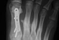
Definitive Fixation of Hand and Wrist Fractures in the Emergency Department
A mentor—now in his 60s—related his experiences as a resident. On call as a second-year resident, he would often be alone at a busy trauma center with no backup. When a case came in, he would quickly read about it in the library, then manage it in the emergency department (ED) if possible, or, if necessary, take the patient to the operating room (OR).
In the era of improved patient care, increased supervision, and decreased autonomy, this is not the reality anymore.1 In theory, more reliable patient care is the result; however, the pendulum may have swung too far.
There are a number of injuries that are amenable to definitive fixation in the ED, but not as limited an array of injuries as we have perhaps grown accustomed to. Hand injuries are among the most common orthopedic injuries seen in the ED, with fractures of the metacarpals and phalanges constituting nearly one-half of all hand injuries.2 The authors recently attended an excellent instructional course lecture on “The Lost and Found Art of Percutaneous Pinning in the Hand and Wrist” at the annual conference of the American Academy of Orthopaedic Surgeons.3 The presenters itemized a comprehensive list of fractures and simple dislocations of the hand, which could be simply, safely, effectively, and definitively managed through percutaneous pinning techniques. A significant number of unstable fractures of the phalanges and metacarpals can be treated in the ED under mini–C-arm fluoroscopy without an admission and trip to the OR.3,4 Most phalangeal and metacarpal fractures are nondisplaced or minimally displaced and stable, and can often be handled with a combination of closed reduction, buddy-taping, and splinting.5 The indications for percutaneous versus internal fixation depend on a number of factors, including bone quality, degree of comminution, quality of the soft-tissue envelope, articular involvement, acuity of presentation, and goals for motion.6,7
Many simple injury patterns involving unstable fractures or dislocations may be definitively managed in the ED with percutaneous pinning (eg, injuries that are unstable with closed reduction alone but that do not necessitate soft-tissue dissection). These include but are not limited to bony mallet injuries, unstable transverse or oblique fractures or fracture-dislocations of the phalanges and metacarpals, carpometacarpal fracture- dislocations, and underlying fractures that need protection of nail-bed repairs, soft-tissue flaps, or extensor tendon injuries (Figures 1, 2).7,8 The techniques for specific fracture types are beyond the scope of this article but are readily available.5,6
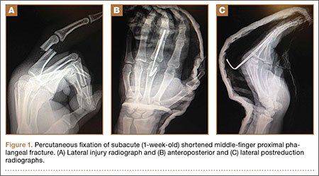
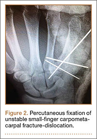
There are certain situations that undoubtedly warrant surgery in the OR, such as neurovascular injury necessitating microvascular repair, flexor tendon laceration, severely comminuted or segmental fractures, irreducible dislocations, and fractures with severe soft-tissue injury or contamination not amenable to primary irrigation, débridement, and closure at bedside.4,7,8
You might ask, “Why would one treat an operative injury in the ED and not formally in the OR?,” and we submit that there are a number of reasons.
First, and most important, with increasing health care costs and decreasing reimbursements, physicians are faced with providing safe but economical care. Percutaneous Kirschner wire (K-wire) fixation is dramatically more cost-effective when performed in the ED than in the OR. The cost of a procedure performed in either setting is similarly dependent on a variety of factors, generally including complexity of the patient or procedure, costs of supplies and pharmacologic agents, fixed versus variable overhead costs, and the professional fees of providers and ancillary personnel.9,10
While the patient is not charged per hour in the ED, it is estimated that ORs in the United States cost, on average, $62 per minute, ranging from as low as $22 to as high as $133 per minute.9 Additionally, the number of personnel involved in running an OR exceeds those for a similar procedure performed in the ED, considering (at a minimum) the orthopedic surgeon, anesthesiologist, scrub and radiology technicians, and nursing personnel required before, during, and after an operation.
While analgesia and procedural sedation can be performed similarly in either setting, it is our experience that patients are managed much more often in the ED with local anesthesia under direct care of only the orthopedic provider, whereas intravenous sedation and general anesthesia are far more commonly implemented in the OR. There are exceptions for pediatric patients or those who are unable to tolerate the procedure under only local anesthesia. Local anesthesia or even intravenous conscious sedation entails less risk as well as lower associated drug costs.11
The difference in risk is especially true for sicker patients undergoing minimally invasive procedures.11 Although administration of adequate procedural analgesia grows increasingly difficult the more proximal the injury, the hand and the fingers are easily and reliably anesthetized with well-placed wrist or digital blocks, with infrequent complications.12 Application of a lidocaine/bupivacaine mixture provides up to 6 to 8 hours of analgesia. A small tourniquet alternative, such as the finger of a sterile glove or phlebotomy tourniquet, applied to the base of the finger or the wrist additionally provides a relatively bloodless field and effectively acts as a Bier block.
Percutaneous pins are much more forgiving than rigid internal fixation. If the initial placement of a pin is unsatisfactory, the pin can be reinserted at little cost.12 Conversely, it may not be possible to reposition a misplaced screw or screw with inadequate purchase and still maintain adequate fixation. While percutaneous pin fixation is not as rigid as screw fixation, the degree of stability provided is adequate for the small forces affecting the hand in most cases. Accordingly, there is a very low incidence of fibrous union or nonunion.13,14 With an increasing appreciation of soft-tissue handling over the past few decades, another significant advantage of K-wire fixation is the obviation of soft-tissue dissection, preserving the biology to maximize healing and minimize adverse sequelae.12 Percutaneous fixation has been shown to achieve functional outcomes comparable to open reduction with internal fixation of operative phalangeal and metacarpal fractures, without soft-tissue disruption, scarring, or implant irritation, and with minimal risk of infection.3,13,15,16 Ultimate range of motion after percutaneous fixation is comparable, if not superior, to that of internal fixation, despite the initial advantage of rigid internal fixation secondary to decreased scarring and lack of indwelling hardware.16,17
While the risk of infection, perhaps the primary concern with percutaneous fixation, has been cited as high as 7%, osteomyelitis is exceedingly rare (<0.5%).3,13,14 Furthermore, pins are often left in place for 3 to 6 weeks, and infection has been found to occur most often at a mean of 10 weeks.7,13 Infection can also be mitigated by intelligent pin placement, relief of residual tension, and splint immobilization.4,15 Pin loosening has similarly been reported in up to 4% of cases in large retrospective studies, occurring at an average of 8 weeks, by which time most pins would have been extricated.13 Other complications related to impaling adjacent neurovascular or tendinous structures have also been cited but are rare.13 A 12-month prospective study of 75 patients specifically evaluating the outcomes after closed reduction with percutaneous fixation of unstable hand fractures in the ED reported only 6 complications at final follow-up.4 Complications were all minor, with no cases of nonunion, delayed union, malunion, pin-tract infection, pyarthrosis, or cellulitis, even in the setting of open fractures. Three patients required revision in the OR for pin migration, initial malreduction, and bone loss in the setting of comminution, respectively. The authors credited their low complication rate to supplementary immobilization.
In conclusion, many unstable simple fractures and dislocations of the hand and wrist can be safely and effectively treated in the ED. While it may seem daunting for a junior resident who is unfamiliar with percutaneous techniques, the authors advocate learning from a more senior mentor. The only additional training required is an understanding of how to apply this skill set in a different setting.
1. Levine WN, Spang RC 3rd. ACGME duty hour requirements: perceptions and impact on resident training and patient care. J Am Acad Orthop Surg. 2014;22(9):535-544.
2. Chung KC, Spilson SV. The frequency and epidemiology of hand and forearm fractures in the United States. J Hand Surg Am. 2001;26(5):908-915.
3. Catalano LW 3rd, Glickel SZ, Strauch RJ, Barron AO. The lost and found art of percutaneous pinning in the hand and wrist. Instructional Course Lectures. Annual Meeting of the American Academy of Orthopaedic Surgeons; March 24, 2015; Las Vegas, NV.
4. Starker I, Eaton RG. Kirschner wire placement in the emergency room. Is there a risk? J Hand Surg Br. 1995;20(4):535-538.
5. Meals C, Meals R. Hand fractures: a review of current treatment strategies. J Hand Surg Am. 2013;38(5):1021-1031.
6. Henry MH. Fractures of the proximal phalanx and metacarpals in the hand: preferred methods of stabilization. J Am Acad Orthop Surg. 2008;16(10):586-595.
7. Klein DM, Belsole RJ. Percutaneous treatment of carpal, metacarpal, and phalangeal injuries. Clin Orthop Relat Res. 2000;(375):116-125.
8. Bernstein ML, Chung KC. Hand fractures and their management: an international view. Injury. 2006;37(11):1043-1048.
9. Macario A. What does one minute of operating room time cost? J Clin Anesth. 2010;22(4):233-236.
10. Williams RM. The costs of visits to emergency departments. N Engl J Med. 1996;334(10):642-646.
11. Bodenham AR, Howell SJ. General anesthesia vs local anaesthesia: an ongoing story. Br J Anaesth. 2009;103(6):785-789.
12. Stern PJ. Management of fractures of the hand over the last 25 years. J Hand Surg Am. 2000;25(5):817-823.
13. Botte MJ, Davis JL, Rose BA, et al. Complications of smooth pin fixation of fractures and dislocations in the hand and wrist. Clin Orthop Relat Res. 1992;(276):194-201.
14. Wray RC Jr, Glunk R. Treatment of delayed union, nonunion, and malunion of the phalanges of the hand. Ann Plast Surg. 1989;22(1):14-18.
15. Hsu LP, Schwartz EG, Kalainov DM, Chen F, Makowiec RL. Complications of K-wire fixation in procedures involving the hand and wrist. J Hand Surg Am. 2011;36(4):610-616.
16. Stem PJ, Wieser MJ, Reilly DG. Complications of plate fixation in the hand skeleton. Clin Orthop Relat Res. 1987;(214):59-65.
17. Page SM, Stern PJ. Complications and range of motion following plate fixation of metacarpal and phalangeal fractures. J Hand Surg Am. 1998;23(5):827-832.
A mentor—now in his 60s—related his experiences as a resident. On call as a second-year resident, he would often be alone at a busy trauma center with no backup. When a case came in, he would quickly read about it in the library, then manage it in the emergency department (ED) if possible, or, if necessary, take the patient to the operating room (OR).
In the era of improved patient care, increased supervision, and decreased autonomy, this is not the reality anymore.1 In theory, more reliable patient care is the result; however, the pendulum may have swung too far.
There are a number of injuries that are amenable to definitive fixation in the ED, but not as limited an array of injuries as we have perhaps grown accustomed to. Hand injuries are among the most common orthopedic injuries seen in the ED, with fractures of the metacarpals and phalanges constituting nearly one-half of all hand injuries.2 The authors recently attended an excellent instructional course lecture on “The Lost and Found Art of Percutaneous Pinning in the Hand and Wrist” at the annual conference of the American Academy of Orthopaedic Surgeons.3 The presenters itemized a comprehensive list of fractures and simple dislocations of the hand, which could be simply, safely, effectively, and definitively managed through percutaneous pinning techniques. A significant number of unstable fractures of the phalanges and metacarpals can be treated in the ED under mini–C-arm fluoroscopy without an admission and trip to the OR.3,4 Most phalangeal and metacarpal fractures are nondisplaced or minimally displaced and stable, and can often be handled with a combination of closed reduction, buddy-taping, and splinting.5 The indications for percutaneous versus internal fixation depend on a number of factors, including bone quality, degree of comminution, quality of the soft-tissue envelope, articular involvement, acuity of presentation, and goals for motion.6,7
Many simple injury patterns involving unstable fractures or dislocations may be definitively managed in the ED with percutaneous pinning (eg, injuries that are unstable with closed reduction alone but that do not necessitate soft-tissue dissection). These include but are not limited to bony mallet injuries, unstable transverse or oblique fractures or fracture-dislocations of the phalanges and metacarpals, carpometacarpal fracture- dislocations, and underlying fractures that need protection of nail-bed repairs, soft-tissue flaps, or extensor tendon injuries (Figures 1, 2).7,8 The techniques for specific fracture types are beyond the scope of this article but are readily available.5,6
There are certain situations that undoubtedly warrant surgery in the OR, such as neurovascular injury necessitating microvascular repair, flexor tendon laceration, severely comminuted or segmental fractures, irreducible dislocations, and fractures with severe soft-tissue injury or contamination not amenable to primary irrigation, débridement, and closure at bedside.4,7,8
You might ask, “Why would one treat an operative injury in the ED and not formally in the OR?,” and we submit that there are a number of reasons.
First, and most important, with increasing health care costs and decreasing reimbursements, physicians are faced with providing safe but economical care. Percutaneous Kirschner wire (K-wire) fixation is dramatically more cost-effective when performed in the ED than in the OR. The cost of a procedure performed in either setting is similarly dependent on a variety of factors, generally including complexity of the patient or procedure, costs of supplies and pharmacologic agents, fixed versus variable overhead costs, and the professional fees of providers and ancillary personnel.9,10
While the patient is not charged per hour in the ED, it is estimated that ORs in the United States cost, on average, $62 per minute, ranging from as low as $22 to as high as $133 per minute.9 Additionally, the number of personnel involved in running an OR exceeds those for a similar procedure performed in the ED, considering (at a minimum) the orthopedic surgeon, anesthesiologist, scrub and radiology technicians, and nursing personnel required before, during, and after an operation.
While analgesia and procedural sedation can be performed similarly in either setting, it is our experience that patients are managed much more often in the ED with local anesthesia under direct care of only the orthopedic provider, whereas intravenous sedation and general anesthesia are far more commonly implemented in the OR. There are exceptions for pediatric patients or those who are unable to tolerate the procedure under only local anesthesia. Local anesthesia or even intravenous conscious sedation entails less risk as well as lower associated drug costs.11
The difference in risk is especially true for sicker patients undergoing minimally invasive procedures.11 Although administration of adequate procedural analgesia grows increasingly difficult the more proximal the injury, the hand and the fingers are easily and reliably anesthetized with well-placed wrist or digital blocks, with infrequent complications.12 Application of a lidocaine/bupivacaine mixture provides up to 6 to 8 hours of analgesia. A small tourniquet alternative, such as the finger of a sterile glove or phlebotomy tourniquet, applied to the base of the finger or the wrist additionally provides a relatively bloodless field and effectively acts as a Bier block.
Percutaneous pins are much more forgiving than rigid internal fixation. If the initial placement of a pin is unsatisfactory, the pin can be reinserted at little cost.12 Conversely, it may not be possible to reposition a misplaced screw or screw with inadequate purchase and still maintain adequate fixation. While percutaneous pin fixation is not as rigid as screw fixation, the degree of stability provided is adequate for the small forces affecting the hand in most cases. Accordingly, there is a very low incidence of fibrous union or nonunion.13,14 With an increasing appreciation of soft-tissue handling over the past few decades, another significant advantage of K-wire fixation is the obviation of soft-tissue dissection, preserving the biology to maximize healing and minimize adverse sequelae.12 Percutaneous fixation has been shown to achieve functional outcomes comparable to open reduction with internal fixation of operative phalangeal and metacarpal fractures, without soft-tissue disruption, scarring, or implant irritation, and with minimal risk of infection.3,13,15,16 Ultimate range of motion after percutaneous fixation is comparable, if not superior, to that of internal fixation, despite the initial advantage of rigid internal fixation secondary to decreased scarring and lack of indwelling hardware.16,17
While the risk of infection, perhaps the primary concern with percutaneous fixation, has been cited as high as 7%, osteomyelitis is exceedingly rare (<0.5%).3,13,14 Furthermore, pins are often left in place for 3 to 6 weeks, and infection has been found to occur most often at a mean of 10 weeks.7,13 Infection can also be mitigated by intelligent pin placement, relief of residual tension, and splint immobilization.4,15 Pin loosening has similarly been reported in up to 4% of cases in large retrospective studies, occurring at an average of 8 weeks, by which time most pins would have been extricated.13 Other complications related to impaling adjacent neurovascular or tendinous structures have also been cited but are rare.13 A 12-month prospective study of 75 patients specifically evaluating the outcomes after closed reduction with percutaneous fixation of unstable hand fractures in the ED reported only 6 complications at final follow-up.4 Complications were all minor, with no cases of nonunion, delayed union, malunion, pin-tract infection, pyarthrosis, or cellulitis, even in the setting of open fractures. Three patients required revision in the OR for pin migration, initial malreduction, and bone loss in the setting of comminution, respectively. The authors credited their low complication rate to supplementary immobilization.
In conclusion, many unstable simple fractures and dislocations of the hand and wrist can be safely and effectively treated in the ED. While it may seem daunting for a junior resident who is unfamiliar with percutaneous techniques, the authors advocate learning from a more senior mentor. The only additional training required is an understanding of how to apply this skill set in a different setting.
1. Levine WN, Spang RC 3rd. ACGME duty hour requirements: perceptions and impact on resident training and patient care. J Am Acad Orthop Surg. 2014;22(9):535-544.
2. Chung KC, Spilson SV. The frequency and epidemiology of hand and forearm fractures in the United States. J Hand Surg Am. 2001;26(5):908-915.
3. Catalano LW 3rd, Glickel SZ, Strauch RJ, Barron AO. The lost and found art of percutaneous pinning in the hand and wrist. Instructional Course Lectures. Annual Meeting of the American Academy of Orthopaedic Surgeons; March 24, 2015; Las Vegas, NV.
4. Starker I, Eaton RG. Kirschner wire placement in the emergency room. Is there a risk? J Hand Surg Br. 1995;20(4):535-538.
5. Meals C, Meals R. Hand fractures: a review of current treatment strategies. J Hand Surg Am. 2013;38(5):1021-1031.
6. Henry MH. Fractures of the proximal phalanx and metacarpals in the hand: preferred methods of stabilization. J Am Acad Orthop Surg. 2008;16(10):586-595.
7. Klein DM, Belsole RJ. Percutaneous treatment of carpal, metacarpal, and phalangeal injuries. Clin Orthop Relat Res. 2000;(375):116-125.
8. Bernstein ML, Chung KC. Hand fractures and their management: an international view. Injury. 2006;37(11):1043-1048.
9. Macario A. What does one minute of operating room time cost? J Clin Anesth. 2010;22(4):233-236.
10. Williams RM. The costs of visits to emergency departments. N Engl J Med. 1996;334(10):642-646.
11. Bodenham AR, Howell SJ. General anesthesia vs local anaesthesia: an ongoing story. Br J Anaesth. 2009;103(6):785-789.
12. Stern PJ. Management of fractures of the hand over the last 25 years. J Hand Surg Am. 2000;25(5):817-823.
13. Botte MJ, Davis JL, Rose BA, et al. Complications of smooth pin fixation of fractures and dislocations in the hand and wrist. Clin Orthop Relat Res. 1992;(276):194-201.
14. Wray RC Jr, Glunk R. Treatment of delayed union, nonunion, and malunion of the phalanges of the hand. Ann Plast Surg. 1989;22(1):14-18.
15. Hsu LP, Schwartz EG, Kalainov DM, Chen F, Makowiec RL. Complications of K-wire fixation in procedures involving the hand and wrist. J Hand Surg Am. 2011;36(4):610-616.
16. Stem PJ, Wieser MJ, Reilly DG. Complications of plate fixation in the hand skeleton. Clin Orthop Relat Res. 1987;(214):59-65.
17. Page SM, Stern PJ. Complications and range of motion following plate fixation of metacarpal and phalangeal fractures. J Hand Surg Am. 1998;23(5):827-832.
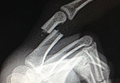
Phenotype HNPP (Hereditary Neuropathy With Liability to Pressure Palsies) Induced by Medical Procedures
PMP22 is a tetra-span membrane protein primarily expressed in myelinating Schwann cells. Heterozygous deletion of the PMP22 gene (1 copy) causes HNPP (hereditary neuropathy with liability to pressure palsies).1 Interestingly, a reciprocal genetic disorder with 3 copies of human PMP22 causes the most common inherited neuropathy, Charcot-Marie-Tooth disease type 1A (CMT1A).2,3 As the reciprocal mutations occur at initiation of gestation, it is expected that HNPP and CMT1A have a similar prevalence. However, studies have shown HNPP prevalence of 2 to 5 cases per 100,000, far below the CMT1A prevalence of 1:5000.4 This finding prompted speculation that many patients with HNPP may be undiagnosed because of the subtlety of the phenotypes.5
Patients with HNPP typically present with focal sensory loss and muscle weakness related to mechanical stress–induced failure of action potential propagation.6,7 In this article, we report the case of an asymptomatic woman with the HNPP mutation. Her focal neurologic deficits occurred only after total knee arthroplasty (TKA), which in healthy patients is not expected to induce focal sensory and motor symptoms. The patient provided written informed consent for print and electronic publication of this case report.
Case Report
The patient, a healthy 57-year-old woman, had a normal developmental history. For decades, she had practiced ballet without any physical difficulties. She underwent left TKA and woke up with a footdrop on the left side. The left foot was less sensitive to temperature. Ankle strength returned 2 months later. There was no family history of HNPP.
The patient was examined by a local neurologist, who found steppage gait, weak ankle dorsiflexion (4 on Medical Research Council scale), and diminished touch on the lateral aspect of the left leg. Deep tendon reflexes were present in the arms but not the legs.
A nerve conduction study (NCS) performed after the footdrop revealed prolonged distal latency and decreased amplitude in the left peroneal and tibial nerves. The left sural nerve was normal. Needle electromyogram revealed denervation changes in the muscles innervated by the left peroneal nerve (Table). In addition, we also performed an NCS on the arm (Table), which was unaffected by the surgical procedure. This NCS revealed severely prolonged distal latency across the left wrist in the median nerve and focal slowing of conduction velocity of the ulnar nerve across the left elbow. These changes provide evidence of asymptomatic carpal tunnel syndrome and ulnar nerve entrapment, typical electrophysiologic abnormalities of HNPP.8As there was no explanation for the footdrop from the surgery, we had a DNA test performed (Athena Diagnostics). This test identified a heterozygous deletion of chromosome 17p12 containing the PMP22 gene, the HNPP mutation.

Discussion
This case had several important features. First, though the patient developed an electrophysiologic phenotype of HNPP, she was completely asymptomatic clinically and very athletic before her medical procedure. She would not have been diagnosed with HNPP if her clinical deficits had not been induced by TKA. Therefore, the prevalence of HNPP is likely underestimated. Second, for patients with the HNPP mutation, there may be serious neurologic consequences of certain medical procedures. The diagnosis of HNPP should be pursued if there is no explanation from the medical procedure per se. In addition, patients with a family history of HNPP should be carefully evaluated before any procedure that may put them at risk for severe peripheral nerve damage, and they should be counseled regarding the risks. It is important to determine the prevalence of HNPP among patients who develop footdrop after knee arthroplasty, as this information could potentially be used to revise ideas about the etiology of peripheral nerve complications of knee arthroplasty. We now describe possible revisions of these ideas.
Footdrop is a rare complication of TKA. Retrospective studies have found its incidence ranging from 0.3% to 1.3%.9-11 The investigators in those studies postulated 3 main causes for peroneal nerve palsy. First, traction may put pressure on the peroneal nerve during normalization of the mechanical axis of a valgus knee. Our patient did not have a valgus knee. Second, epidural hematoma by anesthetic procedure may compress the spinal roots. Our patient received general anesthesia during the procedure; epidural or spinal anesthesia was not used. Third, postoperative dressing may compress the nerve. Our patient did not develop any signs of constrictive dressing, such as inordinate pain, which can be relieved by removing the dressing, and swelling of the leg distal to the dressing. Therefore, her footdrop likely was not a complication of surgery.
This case demonstrates how a patient with undiagnosed HNPP can manifest the HNPP phenotype only after undergoing a particular surgical procedure. HNPP is unfamiliar to most orthopedic surgeons.
1. Chance PF, Alderson MK, Leppig KA, et al. DNA deletion associated with hereditary neuropathy with liability to pressure palsies. Cell. 1993;72(1):143-151.
2. Lupski JR, de Oca-Luna RM, Slaugenhaupt S, et al. DNA duplication associated with Charcot-Marie-Tooth disease type 1A. Cell. 1991;66(2):219-232.
3. Raeymaekers P, Timmerman V, Nelis E, et al. Estimation of the size of the chromosome 17p11.2 duplication in Charcot-Marie-Tooth neuropathy type 1a (CMT1a). HMSN Collaborative Research Group. J Med Genet. 1992;29(1):5-11.
4. Meretoja P, Silander K, Kalimo H, Aula P, Meretoja A, Savontaus ML. Epidemiology of hereditary neuropathy with liability to pressure palsies (HNPP) in south western Finland. Neuromuscul Disord. 1997;7(8):529-532.
5. Li J, Parker B, Martyn C, Natarajan C, Guo J. The PMP22 gene and its related diseases. Mol Neurobiol. 2013;47(2):673-698.
6. Bai Y, Zhang X, Katona I, et al. Conduction block in PMP22 deficiency. J Neurosci. 2010;30(2):600-608.
7. Guo J, Wang L, Zhang Y, et al. Abnormal junctions and permeability of myelin in PMP22-deficient nerves. Ann Neurol. 2014;75(2):255-265.
8. Li J, Krajewski K, Shy ME, Lewis RA. Hereditary neuropathy with liability to pressure palsy: the electrophysiology fits the name. Neurology. 2002;58(12):1769-1773.
9. Rose HA, Hood RW, Otis JC, Ranawat CS, Insall JN. Peroneal-nerve palsy following total knee arthroplasty. A review of the Hospital for Special Surgery experience. J Bone Joint Surg Am. 1982;64(3):347-351.
10. Schinsky MF, Macaulay W, Parks ML, Kiernan H, Nercessian OA. Nerve injury after primary total knee arthroplasty. J Arthroplasty. 2001;16(8):1048-1054.
11. Nercessian OA, Ugwonali OF, Park S. Peroneal nerve palsy after total knee arthroplasty. J Arthroplasty. 2005;20(8):1068-1073.
PMP22 is a tetra-span membrane protein primarily expressed in myelinating Schwann cells. Heterozygous deletion of the PMP22 gene (1 copy) causes HNPP (hereditary neuropathy with liability to pressure palsies).1 Interestingly, a reciprocal genetic disorder with 3 copies of human PMP22 causes the most common inherited neuropathy, Charcot-Marie-Tooth disease type 1A (CMT1A).2,3 As the reciprocal mutations occur at initiation of gestation, it is expected that HNPP and CMT1A have a similar prevalence. However, studies have shown HNPP prevalence of 2 to 5 cases per 100,000, far below the CMT1A prevalence of 1:5000.4 This finding prompted speculation that many patients with HNPP may be undiagnosed because of the subtlety of the phenotypes.5
Patients with HNPP typically present with focal sensory loss and muscle weakness related to mechanical stress–induced failure of action potential propagation.6,7 In this article, we report the case of an asymptomatic woman with the HNPP mutation. Her focal neurologic deficits occurred only after total knee arthroplasty (TKA), which in healthy patients is not expected to induce focal sensory and motor symptoms. The patient provided written informed consent for print and electronic publication of this case report.
Case Report
The patient, a healthy 57-year-old woman, had a normal developmental history. For decades, she had practiced ballet without any physical difficulties. She underwent left TKA and woke up with a footdrop on the left side. The left foot was less sensitive to temperature. Ankle strength returned 2 months later. There was no family history of HNPP.
The patient was examined by a local neurologist, who found steppage gait, weak ankle dorsiflexion (4 on Medical Research Council scale), and diminished touch on the lateral aspect of the left leg. Deep tendon reflexes were present in the arms but not the legs.
A nerve conduction study (NCS) performed after the footdrop revealed prolonged distal latency and decreased amplitude in the left peroneal and tibial nerves. The left sural nerve was normal. Needle electromyogram revealed denervation changes in the muscles innervated by the left peroneal nerve (Table). In addition, we also performed an NCS on the arm (Table), which was unaffected by the surgical procedure. This NCS revealed severely prolonged distal latency across the left wrist in the median nerve and focal slowing of conduction velocity of the ulnar nerve across the left elbow. These changes provide evidence of asymptomatic carpal tunnel syndrome and ulnar nerve entrapment, typical electrophysiologic abnormalities of HNPP.8As there was no explanation for the footdrop from the surgery, we had a DNA test performed (Athena Diagnostics). This test identified a heterozygous deletion of chromosome 17p12 containing the PMP22 gene, the HNPP mutation.
Discussion
This case had several important features. First, though the patient developed an electrophysiologic phenotype of HNPP, she was completely asymptomatic clinically and very athletic before her medical procedure. She would not have been diagnosed with HNPP if her clinical deficits had not been induced by TKA. Therefore, the prevalence of HNPP is likely underestimated. Second, for patients with the HNPP mutation, there may be serious neurologic consequences of certain medical procedures. The diagnosis of HNPP should be pursued if there is no explanation from the medical procedure per se. In addition, patients with a family history of HNPP should be carefully evaluated before any procedure that may put them at risk for severe peripheral nerve damage, and they should be counseled regarding the risks. It is important to determine the prevalence of HNPP among patients who develop footdrop after knee arthroplasty, as this information could potentially be used to revise ideas about the etiology of peripheral nerve complications of knee arthroplasty. We now describe possible revisions of these ideas.
Footdrop is a rare complication of TKA. Retrospective studies have found its incidence ranging from 0.3% to 1.3%.9-11 The investigators in those studies postulated 3 main causes for peroneal nerve palsy. First, traction may put pressure on the peroneal nerve during normalization of the mechanical axis of a valgus knee. Our patient did not have a valgus knee. Second, epidural hematoma by anesthetic procedure may compress the spinal roots. Our patient received general anesthesia during the procedure; epidural or spinal anesthesia was not used. Third, postoperative dressing may compress the nerve. Our patient did not develop any signs of constrictive dressing, such as inordinate pain, which can be relieved by removing the dressing, and swelling of the leg distal to the dressing. Therefore, her footdrop likely was not a complication of surgery.
This case demonstrates how a patient with undiagnosed HNPP can manifest the HNPP phenotype only after undergoing a particular surgical procedure. HNPP is unfamiliar to most orthopedic surgeons.
1. Chance PF, Alderson MK, Leppig KA, et al. DNA deletion associated with hereditary neuropathy with liability to pressure palsies. Cell. 1993;72(1):143-151.
2. Lupski JR, de Oca-Luna RM, Slaugenhaupt S, et al. DNA duplication associated with Charcot-Marie-Tooth disease type 1A. Cell. 1991;66(2):219-232.
3. Raeymaekers P, Timmerman V, Nelis E, et al. Estimation of the size of the chromosome 17p11.2 duplication in Charcot-Marie-Tooth neuropathy type 1a (CMT1a). HMSN Collaborative Research Group. J Med Genet. 1992;29(1):5-11.
4. Meretoja P, Silander K, Kalimo H, Aula P, Meretoja A, Savontaus ML. Epidemiology of hereditary neuropathy with liability to pressure palsies (HNPP) in south western Finland. Neuromuscul Disord. 1997;7(8):529-532.
5. Li J, Parker B, Martyn C, Natarajan C, Guo J. The PMP22 gene and its related diseases. Mol Neurobiol. 2013;47(2):673-698.
6. Bai Y, Zhang X, Katona I, et al. Conduction block in PMP22 deficiency. J Neurosci. 2010;30(2):600-608.
7. Guo J, Wang L, Zhang Y, et al. Abnormal junctions and permeability of myelin in PMP22-deficient nerves. Ann Neurol. 2014;75(2):255-265.
8. Li J, Krajewski K, Shy ME, Lewis RA. Hereditary neuropathy with liability to pressure palsy: the electrophysiology fits the name. Neurology. 2002;58(12):1769-1773.
9. Rose HA, Hood RW, Otis JC, Ranawat CS, Insall JN. Peroneal-nerve palsy following total knee arthroplasty. A review of the Hospital for Special Surgery experience. J Bone Joint Surg Am. 1982;64(3):347-351.
10. Schinsky MF, Macaulay W, Parks ML, Kiernan H, Nercessian OA. Nerve injury after primary total knee arthroplasty. J Arthroplasty. 2001;16(8):1048-1054.
11. Nercessian OA, Ugwonali OF, Park S. Peroneal nerve palsy after total knee arthroplasty. J Arthroplasty. 2005;20(8):1068-1073.
Can Activity Aid Knees In Staying Lubricated?
SAN JOSE—A research team from the University of Delaware has proposed a mechanism that may explain how motion can cause cartilage to reabsorb fluid that leaks out over time.
About 80% of cartilage tissue is composed of synovial fluid that is essential for weight bearing and lubrication of joints. Synovial fluid is easily squeezed out of porous cartilage, decreasing its thickness and leading to joint degradation and osteoarthritis. Yet despite the constant fluid leakage, or deflation, the symptoms of osteoarthritis typically take decades to manifest. The investigator’s study is the latest to determine why this occurs.
Lead researcher David Burris, PhD, Associate Professor of Mechanical Engineering, and his research team tested their theory that the reabsorption process was driven by hydrodynamic pressurization, which occurs when the relative motion of 2 surfaces causes fluid between them to accelerate in the shape of a triangular wedge.

By modeling joint movement using cartilage samples, the team demonstrated that with increased motion (e.g. typical walking speed) the fluid lost as a result of deflation was counteracted by fluid regained through pressurization.
The conclusion, said Dr. Burris, is that, “It is activity itself that combats the natural deflation process associated with interstitial lubrication.” The team presented their findings at the AVS 62nd International Symposium and Exhibition.
The investigators also used in-situ measurements to demonstrate the same fluid recovery process previously observed in-vivo. The researchers presented evidence that fluid drawn into the contact by sliding is pressurized elastohydrodynamically and subsequently forced into the porous articular surfaces to restore hydration.
The new mechanism, which study authors call tribological rehydration, suggests that motion is the engine by which the joint maintains long-term function and health.
“We observed a dynamic competition between input and output [of synovial fluid],” Dr. Burris said. “We know that cartilage thickness is maintained over decades in the joint and this is the first direct insight into why. It is activity itself that combats the natural deflation process associated with interstitial lubrication.”
SAN JOSE—A research team from the University of Delaware has proposed a mechanism that may explain how motion can cause cartilage to reabsorb fluid that leaks out over time.
About 80% of cartilage tissue is composed of synovial fluid that is essential for weight bearing and lubrication of joints. Synovial fluid is easily squeezed out of porous cartilage, decreasing its thickness and leading to joint degradation and osteoarthritis. Yet despite the constant fluid leakage, or deflation, the symptoms of osteoarthritis typically take decades to manifest. The investigator’s study is the latest to determine why this occurs.
Lead researcher David Burris, PhD, Associate Professor of Mechanical Engineering, and his research team tested their theory that the reabsorption process was driven by hydrodynamic pressurization, which occurs when the relative motion of 2 surfaces causes fluid between them to accelerate in the shape of a triangular wedge.
By modeling joint movement using cartilage samples, the team demonstrated that with increased motion (e.g. typical walking speed) the fluid lost as a result of deflation was counteracted by fluid regained through pressurization.
The conclusion, said Dr. Burris, is that, “It is activity itself that combats the natural deflation process associated with interstitial lubrication.” The team presented their findings at the AVS 62nd International Symposium and Exhibition.
The investigators also used in-situ measurements to demonstrate the same fluid recovery process previously observed in-vivo. The researchers presented evidence that fluid drawn into the contact by sliding is pressurized elastohydrodynamically and subsequently forced into the porous articular surfaces to restore hydration.
The new mechanism, which study authors call tribological rehydration, suggests that motion is the engine by which the joint maintains long-term function and health.
“We observed a dynamic competition between input and output [of synovial fluid],” Dr. Burris said. “We know that cartilage thickness is maintained over decades in the joint and this is the first direct insight into why. It is activity itself that combats the natural deflation process associated with interstitial lubrication.”

Does Medication Use Decrease After Hip-Replacement Surgery?
Results of a new study provide information on the trajectories of prescription drug use before and after total hip arthroplasty (THA). The study was published online ahead of print November 14 in Pain.
Researchers merged Norwegian national joint replacement and prescription databases to analyze the medication use of nearly 40,000 patients undergoing THA from 2005 to 2011. The patients’ average age was 68.5 and about three-fourths of patients underwent THA because of primary osteoarthritis.
The investigators analyzed trends in prescription drug use over 2 years: 4 quarters before and 4 quarters after hip-replacement surgery. The study focused on analgesics and hypnotics as well as drugs to treat anxiety and depression.
Overall, about half of patients filled a prescription for an analgesic in the year before surgery. Analgesic use included nonsteroidal anti-inflammatory drugs (NSAIDs) in 38% of patients, opioids in 16%, and other non-opioid analgesics in 12%.
Use of pain medications continued to increase during the last quarter before THA and then increased dramatically in the first quarter after surgery. The sharpest increases were for opioids, which increased to 28% in the last quarter before THA, then to 65% in the first quarter afterward; non-opioid analgesics increased to 21% and then to 60.5%.
The percentage of patients who filled prescriptions for hypnotics also increased from the quarter before to the quarter after surgery—from 14% to 25%. Analysis of the dosage showed a similar pattern.
With continued follow-up after THA, medication use decreased. By 1 year after THA, opioid use had decreased to 14%, NSAID use had decreased to 18%, and non-opioid analgesic use had decreased to 13%. Use of hypnotic drugs also decreased, along with medications to treat anxiety. There was little or no change in the use of antidepressants.
“Patients with chronic pain are frequent users of analgesic and psychotropic drugs and thereby risk adverse drug events,” said Tone Blågestad, a PhD candidate from the Department of Clinical Psychology at the University of Bergen in Norway, and coauthors. They cited special concern about the potential for serious adverse effects of opioids, including drug overdose.

The results suggest that use of pain medications increases in the year before THA, with a further increase immediately afterward, followed by a long-term decrease. That pattern is consistent with previous studies on pain scores in the period before and after THA.
Hypnotic drug use shows a similar trend, suggesting that sleep problems get worse, then improve with long-term pain relief after THA. The lack of change in antidepressant use suggests that depression in patients undergoing hip replacement isn’t necessarily related to hip pain.
“Overall, the present results extend the positive effects of THA to include reduced reliance on medication to alleviate symptoms,” said Ms. Blågestad and colleagues. The finding that hypnotics follow the same prescription trajectory as analgesics highlights the link between pain and sleep. The researchers add, “Our results warrant attention to the increased risk of adverse medication effects occurring with the increased use of both opioids and hypnotics in the recovery phase.”
Suggested Reading
Blågestad T, Nordhus IH, Grønli J, et al. Prescription trajectories and effect of total hip arthroplasty on the use of analgesics, hypnotics, antidepressants and anxiolytics: results from a population of total hip arthroplasty patients. Pain. 2015 Nov 14. [Epub ahead of print].
Results of a new study provide information on the trajectories of prescription drug use before and after total hip arthroplasty (THA). The study was published online ahead of print November 14 in Pain.
Researchers merged Norwegian national joint replacement and prescription databases to analyze the medication use of nearly 40,000 patients undergoing THA from 2005 to 2011. The patients’ average age was 68.5 and about three-fourths of patients underwent THA because of primary osteoarthritis.
The investigators analyzed trends in prescription drug use over 2 years: 4 quarters before and 4 quarters after hip-replacement surgery. The study focused on analgesics and hypnotics as well as drugs to treat anxiety and depression.
Overall, about half of patients filled a prescription for an analgesic in the year before surgery. Analgesic use included nonsteroidal anti-inflammatory drugs (NSAIDs) in 38% of patients, opioids in 16%, and other non-opioid analgesics in 12%.
Use of pain medications continued to increase during the last quarter before THA and then increased dramatically in the first quarter after surgery. The sharpest increases were for opioids, which increased to 28% in the last quarter before THA, then to 65% in the first quarter afterward; non-opioid analgesics increased to 21% and then to 60.5%.
The percentage of patients who filled prescriptions for hypnotics also increased from the quarter before to the quarter after surgery—from 14% to 25%. Analysis of the dosage showed a similar pattern.
With continued follow-up after THA, medication use decreased. By 1 year after THA, opioid use had decreased to 14%, NSAID use had decreased to 18%, and non-opioid analgesic use had decreased to 13%. Use of hypnotic drugs also decreased, along with medications to treat anxiety. There was little or no change in the use of antidepressants.
“Patients with chronic pain are frequent users of analgesic and psychotropic drugs and thereby risk adverse drug events,” said Tone Blågestad, a PhD candidate from the Department of Clinical Psychology at the University of Bergen in Norway, and coauthors. They cited special concern about the potential for serious adverse effects of opioids, including drug overdose.
The results suggest that use of pain medications increases in the year before THA, with a further increase immediately afterward, followed by a long-term decrease. That pattern is consistent with previous studies on pain scores in the period before and after THA.
Hypnotic drug use shows a similar trend, suggesting that sleep problems get worse, then improve with long-term pain relief after THA. The lack of change in antidepressant use suggests that depression in patients undergoing hip replacement isn’t necessarily related to hip pain.
“Overall, the present results extend the positive effects of THA to include reduced reliance on medication to alleviate symptoms,” said Ms. Blågestad and colleagues. The finding that hypnotics follow the same prescription trajectory as analgesics highlights the link between pain and sleep. The researchers add, “Our results warrant attention to the increased risk of adverse medication effects occurring with the increased use of both opioids and hypnotics in the recovery phase.”
Suggested Reading
Blågestad T, Nordhus IH, Grønli J, et al. Prescription trajectories and effect of total hip arthroplasty on the use of analgesics, hypnotics, antidepressants and anxiolytics: results from a population of total hip arthroplasty patients. Pain. 2015 Nov 14. [Epub ahead of print].
Suggested Reading
Blågestad T, Nordhus IH, Grønli J, et al. Prescription trajectories and effect of total hip arthroplasty on the use of analgesics, hypnotics, antidepressants and anxiolytics: results from a population of total hip arthroplasty patients. Pain. 2015 Nov 14. [Epub ahead of print].
