User login
Ischiofemoral Impingement and the Utility of Full-Range-of-Motion Magnetic Resonance Imaging in Its Detection
With the first cases described in 1977, ischiofemoral impingement (IFI) is a relatively recently discovered and less known potential cause of hip pain caused by compression on the quadratus femoris muscle (QFM).1-10 These first patients, who were treated with surgical excision of the lesser trochanter, experienced symptom improvement in all 3 cases.5,7 The most widely accepted diagnostic criteria use a combination of clinical and imaging findings.1-10 Criteria most often cited in the literature include isolated edema-like signal in the QFM on magnetic resonance imaging (MRI) and ipsilateral hip pain without a known cause, such as recent trauma or infection.4,5 All studies describe QFM compression occurring as the muscle passes between the lesser trochanter of the femur and the origin of the ischial tuberosity/hamstring tendons.1-10
Several authors have sought to improve diagnostic accuracy by providing various measurements to quantify the probability of impingement.5,7,9 Although groups have proposed different thresholds, our institution currently uses values reported by Tosun and colleagues5 because theirs is the most robust sample size to date and included 50 patients with IFI.7,9 Although 5 different measurements were proposed, 2 are more commonly cited. The first is the ischiofemoral space (IFS), which is the most narrow distance between the cortex of the lesser trochanter and the cortex of the ischial tuberosity. This space should normally be greater than 1.8 cm.5 The second measurement is called the quadratus femoris space (QFS) and is the most narrow distance between the hamstring tendons and either the iliopsoas tendon or the cortex of the lesser trochanter. The QFS should normally be greater than 1.0 cm.5 However, because these measurements may depend on the hip position during imaging, full-range-of-motion (FROM) MRI may increase diagnostic yield. At our institution, patients are usually imaged supine in neutral position (with respect to internal or external rotation).
In this article, we briefly review IFI, provide an example of how FROM MRI can improve diagnostic accuracy, describe our FROM protocol, and propose an expanded definition of the impingement criteria. The patient provided written informed consent for print and electronic publication of the case details and images.
Full–Range-of-Motion MRI Technique
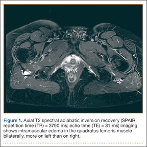
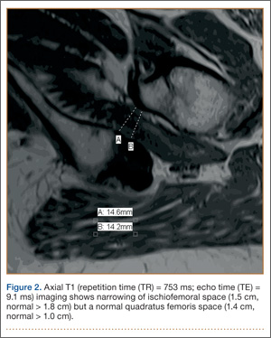
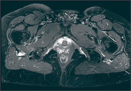
A 58-year-old woman with no surgical history or diagnosed inflammatory arthropathy presented to the department of physical medicine and rehabilitation with left-buttock pain radiating down the left thigh. Despite nonsurgical management with nonsteroidal anti-inflammatory medication, exercise therapy, use of a transcutaneous electrical nerve stimulator unit, and oral corticosteroid therapy, the pain continued. The patient was referred for MRI, and routine static imaging of the pelvis was performed. Although edema-like signal was present in both QFMs (Figure 1), left more than right, the measurement of the QFS and IFS did not meet all criteria for narrowing as described in previous studies. On the symptomatic left side, the IFS measured 1.5 cm and the QFS measured 1.4 cm (Figure 2). On the same side, the distance between the cortex of the greater trochanter and the cortex of the ischial tuberosity, proposed adapted IFS, measured 1.4 cm, and the distance between the cortex of the greater trochanter and the hamstring tendons origin, proposed adapted QFS, measured 1.1 cm (Figure 3). However, because of the isolated QFM edema, refractory buttock and thigh pain, and exclusion of other diagnoses (such as labral tear, bone marrow edema/stress reaction in the hip, or MRI findings of sciatic neuropathy), we determined that the patient needed evaluation of the QFS and the IFS through a full range of motion. The patient returned for the FROM MRI 16 days after the initial static MRI.
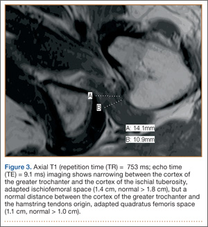
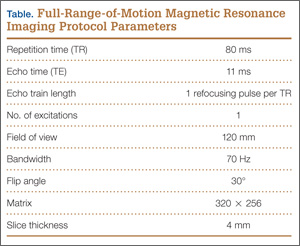
Our FROM MRI was performed on a Magnetom Skyra 3 Tesla magnet (Seimens Healthcare Global, Munich, Germany), using a body array 18-channel coil and a table spine coil. In a supine position, the patient’s imaging started with the hip in extension, adduction, and approximately 20º of internal rotation. During imaging acquisition, the patient was maintained in adduction and extension while the hip was passively externally rotated (Figure 3). A technologist assisted the patient in maintaining the position through a 60º arc of external rotation, while an axial-gradient echo sequence was used to obtain sequential images through the entire arc. Selected parameters are listed in the Table. Acquisition of the arc of motion in the axial plane requires approximately 3 minutes per hip to generate between 8 and 10 images.
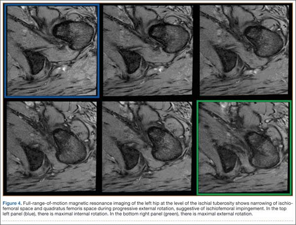
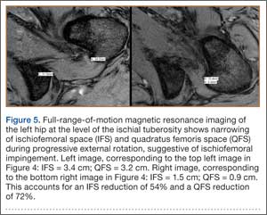
With the patient’s hip in internal rotation, narrowing between the ischium or hamstring tendons and the lesser trochanter did not meet all of the criteria described by Tosun and colleagues5 or Torriani and colleagues.7 However, when the patient shifted into external rotation, the distance between the ischial tuberosity and the greater trochanter, and between the hamstring tendons origin and the greater trochanter, significantly narrowed. The adapted IFS decreased from 3.4 cm to 1.5 cm, and the adapted QFS decreased from 3.2 cm to 0.9 cm, accounting for a 54% and 72% reduction of the adapted IFS and QFS, respectively, with maximum external rotation (Figures 4, 5).
Discussion
While femoroacetabular impingement is a widely recognized and sometimes surgically treated syndrome, IFI may be overlooked as a cause of hip pain. Although IFI is traditionally described as mass effect on the QFM by the ischium/hamstring tendons origin and the lesser trochanter, we propose expansion of this criteria to include narrowing resulting from the greater trochanter in external rotation as a potential source of impingement. By use of FROM MRI, we adapted measurements previously described for IFI to evaluate for compression of the QFM by adjacent osseous and tendinous structures throughout the full range of internal/external hip rotation. In this case, FROM imaging provided evidence of possible anatomical narrowing caused by the greater trochanter, in addition to that caused by the lesser trochanter. Given that impingement may be caused by either the greater or lesser trochanters, it is prudent to perform FROM MRI in evaluating patients with suspected IFI. If FROM imaging is not feasible, static imaging in both maximal internal and external rotation may allow for better assessment. There have been no large studies conducted to assess the normal interval between the ischial tuberosity/hamstring origins and the greater trochanter.
The purpose of this report is to call attention to a source of impingement that may be undetected with static MRI, possibly leading to a missed diagnosis. While we believe this to be the first reported example of impingement involving the greater trochanter, larger studies should be conducted to explore this possible source of impingement. Information about the incidence of greater trochanteric impingement could lead to changes in our understanding of this syndrome and its management.
1. Lee S, Kim I, Lee SM, Lee J. Ischiofemoral impingement syndrome. Ann Rehabil Med. 2013;37(1):143-146.
2. Sussman WI, Han E, Schuenke MD. Quantitative assessment of the ischiofemoral space and evidence of degenerative changes in the quadratus femoris muscle. Surg Radiol Anat. 2013;35(4):273-281.
3. López-Sánchez MC, Armesto Pérez V, Montero Furelos LÁ, Vázquez-Rodríguez TR, Calvo Arrojo G, Díaz Román TM. Ischiofemoral impingement: hip pain of infrequent cause. Ischiofemoral impingement: hip pain of infrequent cause. Rheumatol Clin. 2013;9(3):186-187.
4. Viala P, Vanel D, Larbi A, Cyteval C, Laredo JD. Bilateral ischiofemoral impingement in a patient with hereditary multiple exostoses. Skeletal Radiol. 2012;41(12):1637-1640.
5. Tosun O, Algin O, Yalcin N, Cay N, Ocakoglu G, Karaoglanoglu M. Ischiofemoral impingement: evaluation with new MRI parameters and assessment of their reliability. Skeletal Radiol. 2012;41(5):575-587.
6. Ali AM, Whitwell D, Ostlere SJ. Case report: imaging and surgical treatment of a snapping hip due to ischiofemoral impingement. Skeletal Radiol. 2011;40(5):653-656.
7. Torriani M, Souto SC, Thomas BJ, Ouellette H, Bredella MA. Ischiofemoral impingement syndrome: an entity with hip pain and abnormalities of the quadratus femoris muscle. AJR Am J Roentgenol. 2009;193(1):186-190.
8. Ali AM, Teh J, Whitwell D, Ostlere S. Ischiofemoral impingement: a retrospective analysis of cases in a specialist orthopaedic centre over a four-year period. Hip Int. 2013;3(23):263-268.
9. Sussman WI, Han E, Schuenke MD. Quantitative assessment of the ischiofemoral space and evidence of degenerative changes in the quadratus femoris muscle. Surg Radiol Anat. 2013;35(4):273-281.
10. Kassarjian A. Signal abnormalities in the quadratus femoris muscle: tear or impingement? AJR Am J Roentgenol. 2008;190(6):W379.
With the first cases described in 1977, ischiofemoral impingement (IFI) is a relatively recently discovered and less known potential cause of hip pain caused by compression on the quadratus femoris muscle (QFM).1-10 These first patients, who were treated with surgical excision of the lesser trochanter, experienced symptom improvement in all 3 cases.5,7 The most widely accepted diagnostic criteria use a combination of clinical and imaging findings.1-10 Criteria most often cited in the literature include isolated edema-like signal in the QFM on magnetic resonance imaging (MRI) and ipsilateral hip pain without a known cause, such as recent trauma or infection.4,5 All studies describe QFM compression occurring as the muscle passes between the lesser trochanter of the femur and the origin of the ischial tuberosity/hamstring tendons.1-10
Several authors have sought to improve diagnostic accuracy by providing various measurements to quantify the probability of impingement.5,7,9 Although groups have proposed different thresholds, our institution currently uses values reported by Tosun and colleagues5 because theirs is the most robust sample size to date and included 50 patients with IFI.7,9 Although 5 different measurements were proposed, 2 are more commonly cited. The first is the ischiofemoral space (IFS), which is the most narrow distance between the cortex of the lesser trochanter and the cortex of the ischial tuberosity. This space should normally be greater than 1.8 cm.5 The second measurement is called the quadratus femoris space (QFS) and is the most narrow distance between the hamstring tendons and either the iliopsoas tendon or the cortex of the lesser trochanter. The QFS should normally be greater than 1.0 cm.5 However, because these measurements may depend on the hip position during imaging, full-range-of-motion (FROM) MRI may increase diagnostic yield. At our institution, patients are usually imaged supine in neutral position (with respect to internal or external rotation).
In this article, we briefly review IFI, provide an example of how FROM MRI can improve diagnostic accuracy, describe our FROM protocol, and propose an expanded definition of the impingement criteria. The patient provided written informed consent for print and electronic publication of the case details and images.
Full–Range-of-Motion MRI Technique
A 58-year-old woman with no surgical history or diagnosed inflammatory arthropathy presented to the department of physical medicine and rehabilitation with left-buttock pain radiating down the left thigh. Despite nonsurgical management with nonsteroidal anti-inflammatory medication, exercise therapy, use of a transcutaneous electrical nerve stimulator unit, and oral corticosteroid therapy, the pain continued. The patient was referred for MRI, and routine static imaging of the pelvis was performed. Although edema-like signal was present in both QFMs (Figure 1), left more than right, the measurement of the QFS and IFS did not meet all criteria for narrowing as described in previous studies. On the symptomatic left side, the IFS measured 1.5 cm and the QFS measured 1.4 cm (Figure 2). On the same side, the distance between the cortex of the greater trochanter and the cortex of the ischial tuberosity, proposed adapted IFS, measured 1.4 cm, and the distance between the cortex of the greater trochanter and the hamstring tendons origin, proposed adapted QFS, measured 1.1 cm (Figure 3). However, because of the isolated QFM edema, refractory buttock and thigh pain, and exclusion of other diagnoses (such as labral tear, bone marrow edema/stress reaction in the hip, or MRI findings of sciatic neuropathy), we determined that the patient needed evaluation of the QFS and the IFS through a full range of motion. The patient returned for the FROM MRI 16 days after the initial static MRI.
Our FROM MRI was performed on a Magnetom Skyra 3 Tesla magnet (Seimens Healthcare Global, Munich, Germany), using a body array 18-channel coil and a table spine coil. In a supine position, the patient’s imaging started with the hip in extension, adduction, and approximately 20º of internal rotation. During imaging acquisition, the patient was maintained in adduction and extension while the hip was passively externally rotated (Figure 3). A technologist assisted the patient in maintaining the position through a 60º arc of external rotation, while an axial-gradient echo sequence was used to obtain sequential images through the entire arc. Selected parameters are listed in the Table. Acquisition of the arc of motion in the axial plane requires approximately 3 minutes per hip to generate between 8 and 10 images.
With the patient’s hip in internal rotation, narrowing between the ischium or hamstring tendons and the lesser trochanter did not meet all of the criteria described by Tosun and colleagues5 or Torriani and colleagues.7 However, when the patient shifted into external rotation, the distance between the ischial tuberosity and the greater trochanter, and between the hamstring tendons origin and the greater trochanter, significantly narrowed. The adapted IFS decreased from 3.4 cm to 1.5 cm, and the adapted QFS decreased from 3.2 cm to 0.9 cm, accounting for a 54% and 72% reduction of the adapted IFS and QFS, respectively, with maximum external rotation (Figures 4, 5).
Discussion
While femoroacetabular impingement is a widely recognized and sometimes surgically treated syndrome, IFI may be overlooked as a cause of hip pain. Although IFI is traditionally described as mass effect on the QFM by the ischium/hamstring tendons origin and the lesser trochanter, we propose expansion of this criteria to include narrowing resulting from the greater trochanter in external rotation as a potential source of impingement. By use of FROM MRI, we adapted measurements previously described for IFI to evaluate for compression of the QFM by adjacent osseous and tendinous structures throughout the full range of internal/external hip rotation. In this case, FROM imaging provided evidence of possible anatomical narrowing caused by the greater trochanter, in addition to that caused by the lesser trochanter. Given that impingement may be caused by either the greater or lesser trochanters, it is prudent to perform FROM MRI in evaluating patients with suspected IFI. If FROM imaging is not feasible, static imaging in both maximal internal and external rotation may allow for better assessment. There have been no large studies conducted to assess the normal interval between the ischial tuberosity/hamstring origins and the greater trochanter.
The purpose of this report is to call attention to a source of impingement that may be undetected with static MRI, possibly leading to a missed diagnosis. While we believe this to be the first reported example of impingement involving the greater trochanter, larger studies should be conducted to explore this possible source of impingement. Information about the incidence of greater trochanteric impingement could lead to changes in our understanding of this syndrome and its management.
1. Lee S, Kim I, Lee SM, Lee J. Ischiofemoral impingement syndrome. Ann Rehabil Med. 2013;37(1):143-146.
2. Sussman WI, Han E, Schuenke MD. Quantitative assessment of the ischiofemoral space and evidence of degenerative changes in the quadratus femoris muscle. Surg Radiol Anat. 2013;35(4):273-281.
3. López-Sánchez MC, Armesto Pérez V, Montero Furelos LÁ, Vázquez-Rodríguez TR, Calvo Arrojo G, Díaz Román TM. Ischiofemoral impingement: hip pain of infrequent cause. Ischiofemoral impingement: hip pain of infrequent cause. Rheumatol Clin. 2013;9(3):186-187.
4. Viala P, Vanel D, Larbi A, Cyteval C, Laredo JD. Bilateral ischiofemoral impingement in a patient with hereditary multiple exostoses. Skeletal Radiol. 2012;41(12):1637-1640.
5. Tosun O, Algin O, Yalcin N, Cay N, Ocakoglu G, Karaoglanoglu M. Ischiofemoral impingement: evaluation with new MRI parameters and assessment of their reliability. Skeletal Radiol. 2012;41(5):575-587.
6. Ali AM, Whitwell D, Ostlere SJ. Case report: imaging and surgical treatment of a snapping hip due to ischiofemoral impingement. Skeletal Radiol. 2011;40(5):653-656.
7. Torriani M, Souto SC, Thomas BJ, Ouellette H, Bredella MA. Ischiofemoral impingement syndrome: an entity with hip pain and abnormalities of the quadratus femoris muscle. AJR Am J Roentgenol. 2009;193(1):186-190.
8. Ali AM, Teh J, Whitwell D, Ostlere S. Ischiofemoral impingement: a retrospective analysis of cases in a specialist orthopaedic centre over a four-year period. Hip Int. 2013;3(23):263-268.
9. Sussman WI, Han E, Schuenke MD. Quantitative assessment of the ischiofemoral space and evidence of degenerative changes in the quadratus femoris muscle. Surg Radiol Anat. 2013;35(4):273-281.
10. Kassarjian A. Signal abnormalities in the quadratus femoris muscle: tear or impingement? AJR Am J Roentgenol. 2008;190(6):W379.
Patient Safety: Innovation and Critical Thinking
Preventable medical errors rank as the third most common cause of death in the United States after heart disease and cancer.1 They are responsible for 400,000 deaths each year (over 1095 per day) and another 10,000 serious complications resulting from medical errors each day.1 That is the equivalent of two 747 airliner midair crashes per day. The economic cost to our nation is $1 trillion per year.1
On July 17, 2014, the US Senate Subcommittee on Primary Health and Aging met to address this crisis. Participants included senators and John James, PhD, Founder, Patient Safety America, Houston, Texas; Ashish Jha, MD, MPH, Professor of Health Policy and Management, Harvard School of Public Health, Boston, Massachusetts; Tejal Gandhi, MD, MPH, President, National Patient Safety Foundation, and Associate Professor of Medicine, Harvard Medical School, Boston, Massachusetts; Peter Pronovost, MD, PhD, Senior Vice President for Patient Safety and Quality, and Director of the Armstrong Institute for Patient Safety and Quality, Johns Hopkins Medicine, Baltimore, Maryland; Joanne Disch, PhD, RN, Professor ad Honorem, University of Minnesota School of Nursing, Minneapolis, Minnesota; and Lisa McGiffert, Director, Safe Patient Project, Consumers Union, Austin, Texas. While each speaker suggested various strategies for improving patient safety, they all agreed that information technology is not living up to our expectations for meeting this need. They also agreed that health care has become increasingly “high tech and low touch,” and, as a result, the medical community is leveraging neither technology nor the knowledge accrued from individual patient/physician interactions to improve patient safety and outcomes.1
Last year my mother had a spinal fusion. The surgery was a success by all measures. Two days after she was discharged home, she became weak and was unable to walk. She went to the emergency room, where it was noted that she was severely hyponatremic, weak, and experiencing severe back pain. For the next 36 hours she was not seen by a physician or physician assistant (PA), as the PA who admitted her to the hospital had not notified the “team” that she was admitted. My father, who is a vascular surgeon, notified her spine surgeon, who came to see her. Her hyponatremia was markedly worse, and she was transferred to the intensive care unit (ICU). She continued to decline and was started on hypertonic intravenous (IV) saline. Over the next several days her hyponatremia improved, and she was transferred out of the ICU but continued to have pain. The spine surgeon examined her several times, and imaging showed no evidence of epidural bleeding, infection, or misplaced hardware.
Over the next several days, I was informed by family members that the nurses were “keeping the pain in check” with IV narcotics and that my mom was heavily sedated most of the time. My dad later informed me that she had a foot drop on the left, and the next day another family member told me the foot drop was on the right. My dad and stepbrother each assured me that they were right. When my mom could talk, she told me how weak she was and that sometimes it was her right leg and other times her left. She was seen by a neurologist on 6 out of the next 10 days and underwent 3 computed tomography scans and magnetic resonance imaging, and the neurologist assured us that she had not had a stroke. On a Friday evening, I called my mom, who was progressively short of breath, and she told me that she felt weaker and weaker each day. The “foot drop,” which was now bilateral according to the neurologist, was from “not using it while she was in the ICU.”
My mom, who is an artist, commented that she was having trouble using her hands now and unable to hold a cup. I called the physician on call, who assured me that she was taking care of my mom’s blood pressure (which was labile for the first time ever; she had no history of hypertension) and her pain score was a 5. I explained that I knew that she was not “looking to play mystery diagnosis with an orthopedic surgeon 500 miles away, but I think my mom has Guillain-Barré syndrome.” Fortunately, the doctor said, “Oh my god, I think you’re right.” Monday morning, her diagnosis was confirmed and she has made a remarkable recovery. So how is it that she could be seen by a neurologist and a team of nurses, doctors, therapists, and resident staff and no one made a diagnosis? Certainly contributing factors include a system of multiple medical teams with frequent turnovers and a desire to consult others but no real “quarterback” who was looking at the overall care in a responsible and critical way. A thorough history and physical examination, rather than a multitude of expensive and unnecessary imaging studies, could certainly have led to a quicker diagnosis and avoidance of a protracted hospital stay and rehabilitation.
To be sure, there are many factors that lead to delays in diagnosis. The reliance on advanced imaging, the lack of a simple physical examination, and the lack of critical thinking played prominently in the failure to make a diagnosis in my mom’s case. Some would argue that we need information technology (IT) systems that will allow us to better diagnose and treat patients. They believe that with electronic medical records (EMRs) data points will be entered and a diagnosis will be made. Major corporations like IBM and GE are working to make this a reality. Although Watson (the artificially intelligent computer system created by IBM) may be able to win on Jeopardy and may move the needle forward to improving patient care, 2 things are certain: (1) Appropriate data will need to be input by people, and (2) without critical thinking, the appropriate data can’t be entered or interpreted correctly.
The fact remains that EMR has fallen short of expectations. We have more data at our fingertips but this has not translated into a significant improvement in patient safety. The human factor remains critical. Even though industry and health care workers strive to innovate and merge technological advances with improved patient outcomes, technology will continue to fall short of expectations without the input of critical thinking. There are things that computers and technological advances can do that people can’t, and there are things that people can do that computers can’t.
We cannot become a profession reliant on technology to substitute for critical thinking, and we cannot become a profession that doesn’t recognize what technology can bring to us and our patients. Like a railroad track that needs 2 parallel tracks to move trains, we must continue to build on 2 tracks: innovation and critical thinking. ◾
Reference
1. McCann E. Deaths by medical mistakes hit records. Healthcare IT News. http://www.healthcareitnews.com/news/deaths-by-medical-mistakes-hit-records. Published July 18, 2014. Accessed November 17, 2014.
Preventable medical errors rank as the third most common cause of death in the United States after heart disease and cancer.1 They are responsible for 400,000 deaths each year (over 1095 per day) and another 10,000 serious complications resulting from medical errors each day.1 That is the equivalent of two 747 airliner midair crashes per day. The economic cost to our nation is $1 trillion per year.1
On July 17, 2014, the US Senate Subcommittee on Primary Health and Aging met to address this crisis. Participants included senators and John James, PhD, Founder, Patient Safety America, Houston, Texas; Ashish Jha, MD, MPH, Professor of Health Policy and Management, Harvard School of Public Health, Boston, Massachusetts; Tejal Gandhi, MD, MPH, President, National Patient Safety Foundation, and Associate Professor of Medicine, Harvard Medical School, Boston, Massachusetts; Peter Pronovost, MD, PhD, Senior Vice President for Patient Safety and Quality, and Director of the Armstrong Institute for Patient Safety and Quality, Johns Hopkins Medicine, Baltimore, Maryland; Joanne Disch, PhD, RN, Professor ad Honorem, University of Minnesota School of Nursing, Minneapolis, Minnesota; and Lisa McGiffert, Director, Safe Patient Project, Consumers Union, Austin, Texas. While each speaker suggested various strategies for improving patient safety, they all agreed that information technology is not living up to our expectations for meeting this need. They also agreed that health care has become increasingly “high tech and low touch,” and, as a result, the medical community is leveraging neither technology nor the knowledge accrued from individual patient/physician interactions to improve patient safety and outcomes.1
Last year my mother had a spinal fusion. The surgery was a success by all measures. Two days after she was discharged home, she became weak and was unable to walk. She went to the emergency room, where it was noted that she was severely hyponatremic, weak, and experiencing severe back pain. For the next 36 hours she was not seen by a physician or physician assistant (PA), as the PA who admitted her to the hospital had not notified the “team” that she was admitted. My father, who is a vascular surgeon, notified her spine surgeon, who came to see her. Her hyponatremia was markedly worse, and she was transferred to the intensive care unit (ICU). She continued to decline and was started on hypertonic intravenous (IV) saline. Over the next several days her hyponatremia improved, and she was transferred out of the ICU but continued to have pain. The spine surgeon examined her several times, and imaging showed no evidence of epidural bleeding, infection, or misplaced hardware.
Over the next several days, I was informed by family members that the nurses were “keeping the pain in check” with IV narcotics and that my mom was heavily sedated most of the time. My dad later informed me that she had a foot drop on the left, and the next day another family member told me the foot drop was on the right. My dad and stepbrother each assured me that they were right. When my mom could talk, she told me how weak she was and that sometimes it was her right leg and other times her left. She was seen by a neurologist on 6 out of the next 10 days and underwent 3 computed tomography scans and magnetic resonance imaging, and the neurologist assured us that she had not had a stroke. On a Friday evening, I called my mom, who was progressively short of breath, and she told me that she felt weaker and weaker each day. The “foot drop,” which was now bilateral according to the neurologist, was from “not using it while she was in the ICU.”
My mom, who is an artist, commented that she was having trouble using her hands now and unable to hold a cup. I called the physician on call, who assured me that she was taking care of my mom’s blood pressure (which was labile for the first time ever; she had no history of hypertension) and her pain score was a 5. I explained that I knew that she was not “looking to play mystery diagnosis with an orthopedic surgeon 500 miles away, but I think my mom has Guillain-Barré syndrome.” Fortunately, the doctor said, “Oh my god, I think you’re right.” Monday morning, her diagnosis was confirmed and she has made a remarkable recovery. So how is it that she could be seen by a neurologist and a team of nurses, doctors, therapists, and resident staff and no one made a diagnosis? Certainly contributing factors include a system of multiple medical teams with frequent turnovers and a desire to consult others but no real “quarterback” who was looking at the overall care in a responsible and critical way. A thorough history and physical examination, rather than a multitude of expensive and unnecessary imaging studies, could certainly have led to a quicker diagnosis and avoidance of a protracted hospital stay and rehabilitation.
To be sure, there are many factors that lead to delays in diagnosis. The reliance on advanced imaging, the lack of a simple physical examination, and the lack of critical thinking played prominently in the failure to make a diagnosis in my mom’s case. Some would argue that we need information technology (IT) systems that will allow us to better diagnose and treat patients. They believe that with electronic medical records (EMRs) data points will be entered and a diagnosis will be made. Major corporations like IBM and GE are working to make this a reality. Although Watson (the artificially intelligent computer system created by IBM) may be able to win on Jeopardy and may move the needle forward to improving patient care, 2 things are certain: (1) Appropriate data will need to be input by people, and (2) without critical thinking, the appropriate data can’t be entered or interpreted correctly.
The fact remains that EMR has fallen short of expectations. We have more data at our fingertips but this has not translated into a significant improvement in patient safety. The human factor remains critical. Even though industry and health care workers strive to innovate and merge technological advances with improved patient outcomes, technology will continue to fall short of expectations without the input of critical thinking. There are things that computers and technological advances can do that people can’t, and there are things that people can do that computers can’t.
We cannot become a profession reliant on technology to substitute for critical thinking, and we cannot become a profession that doesn’t recognize what technology can bring to us and our patients. Like a railroad track that needs 2 parallel tracks to move trains, we must continue to build on 2 tracks: innovation and critical thinking. ◾
Reference
1. McCann E. Deaths by medical mistakes hit records. Healthcare IT News. http://www.healthcareitnews.com/news/deaths-by-medical-mistakes-hit-records. Published July 18, 2014. Accessed November 17, 2014.
Reference
1. McCann E. Deaths by medical mistakes hit records. Healthcare IT News. http://www.healthcareitnews.com/news/deaths-by-medical-mistakes-hit-records. Published July 18, 2014. Accessed November 17, 2014.

Application of Epoxy Resin to a Solid-Foam Pelvic Model: Creating a Dry-Erase Pelvis
The value of preoperative planning and templating has been well-established in fracture surgery.1,2 Traditionally, this involves writing a surgical tactic and tracing the radiographs on paper to plan the ultimate reduction and implant placement.1 The advent of sophisticated computer programs has allowed electronic preoperative planning in trauma and arthroplasty surgery.3,4 Software for computer templating of acetabular fractures is available.5 Still, the renderings generated in these exercises are 2-dimensional, and their quality is somewhat dependent on the surgeon’s artistic ability. Ultimately, drawing a fracture is meant to help the surgeon understand its 3-dimensional (3-D) characteristics. This can be difficult working in 2 dimensions especially for bones, such as the pelvis, with complex 3-D structures. A useful alternative is to draw the fracture on a plastic-bone model.
We plan all acetabular fracture surgeries on 3-D models (plastic bones). These models are commonly provided to residents and fellows through educational courses or can be purchased online. Residents, fellows, and staff have their own models for planning, and we typically keep several models in the operating room for teaching before the surgery. Although these models are ideal for visualizing the bony anatomy, they are less than ideal for drawing fracture lines. Ink pens do not leave lines, and lines from markers and pencils cannot be easily erased. After a few planning sessions, the models typically look like a city map, making it difficult to tell the current fracture from those previously evaluated.
Here we describe a technique for turning standard plastic models into white boards so that lines can be drawn clearly with a marker and easily erased. To facilitate the correction of errors and reuse for future cases, we coat pelvic models with dry-erase epoxy resin. Although there is a commercially available product that has similar capabilities, our technique creates a significantly less expensive model that will likely be appealing to residents and fellows.
Technique
Throughout the process of creating the pelvic model, it is important to work in a well-ventilated area. Gloves should be worn at all times. The working surface should be protected with an impervious plastic sheet to avoid primer or epoxy soaking through.
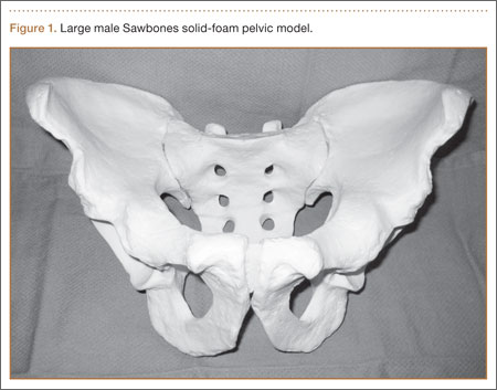
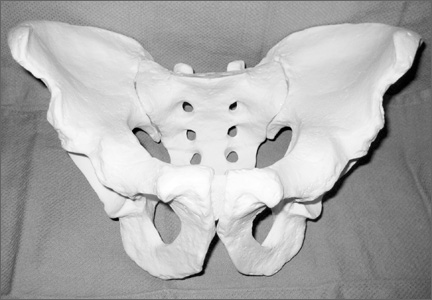
In creating our dry-erase pelvic models, we use the Sawbones large male solid-foam pelvic model (Figure 1; Model 1301, Pacific Research Laboratories, Vashon, Washington). These models are often available to residents and fellows after Arbeitsgemeinschaft für Osteosynthesefragen/Orthopaedic Trauma Association (AO/OTA) trauma courses or resident educational sessions. Alternatively, they can be purchased online.
We sand the model to smooth out surface irregularities and to prepare it to accept primer. First, use 100-grit and then 220-grit sandpaper to create the optimum surface. We recommend suspending the pelvis from string by placing an eyelet screw into the top of the sacrum or looping a string through 1 of the sacral foramen while priming, painting, and curing. To prime the pelvic model, we have used KILZ original spray primer (Masterchem Industries, Imperial, Missouri). It is important that the entire model be well coated with primer because the epoxy resin will not adhere to unprimed plastic-foam surface. Take care to apply an even coat and to avoid drip formation.
Once the primer is completely dry, apply the dry-erase epoxy resin (Rust-Oleum, Vernon Hills, Illinois). Mix the 2 parts of the epoxy resin and apply to the pelvic model with a foam brush. It is important to cover the entire surface of the model with enough epoxy to give a smooth, even finish. This requires 2 to 3 coats applied approximately 30 minutes apart (the epoxy will remain wet but will take additional coats well).
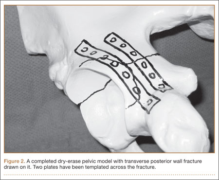
Once the final coat has been applied, the model takes about 48 hours to cure. Hang in a dry, well-ventilated location until it is fully cured. Then, use a dry-erase marker to trace fracture lines and the planned location of plates and screws (Figure 2).
An alternative to creating a dry-erase pelvis is to create a blackboard pelvis. Use Chalkboard Spray (Rust-Oleum) to create a surface that will accept white and colored chalk. The application of this product is much easier than the dry-erase epoxy, because it can be applied in a similar fashion as the spray primer. This creates a black model that can be marked with chalk. However, we have found these models to be less useful than the dry-erase versions, because chalk leaves less precise lines and is harder to remove from the model.
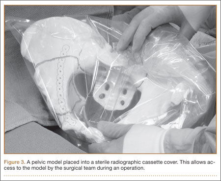
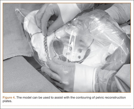
Once created, the pelvic model can be used intraoperatively to help understand fracture reduction and to facilitate the precontouring of pelvic and acetabular plates. We place the model in a sterile radiographic cassette bag (Figure 3). This gives the operating team access to the model and is useful in teaching anatomy, and particularly, screw placement. Further, the model allows an assistant to precontour plates to the model during the exposure portion of the case (Figure 4). While the precontoured plate is not always a perfect fit, it can usually be adjusted easily to fit the unique anatomy of the patient.
Discussion
Understanding the complex anatomy of pelvic and acetabular fractures can be challenging. We use models in the teaching of anatomy, in the interpretation of radiographs and computed tomography (CT) scans, and in preoperative planning. Fracture lines are traced on the pelvic model based on radiographs and/or CT scans and then compared with 3-D reconstruction images and, eventually, with operative findings. The use of our dry-erase models allows for easy correction of mistakes and reuse for further cases.
We have found dry-erase pelvic models to be an invaluable tool for resident and fellow education. While conventional 2-dimensional planning is adequate for most long-bone and periarticular fractures, the creation of these 3-D planning tools is useful in understanding the anatomy and surgical treatment of pelvic and acetabular fractures.
1. Reudi TP, Buckley R, Moran C. AO Principles of Fracture Management. New York, NY: Thieme; 2007.
2. Mast J, Jakob R, Ganz R. Planning & Reduction Techniques in Fracture Surgery. Berlin, Germany: Springer-Verlag; 2006.
3. Pilson HT, Reddix RN Jr, Mutty CE, Webb LX. The long lost art of preoperative planning—resurrected? Orthopedics. 2008;31(12):1238.
4. Unnanuntana A, Wagner D, Goodman SB. The accuracy of preoperative templating in cementless total hip arthroplasty. J Arthroplasty. 2009;24(2):180-186.
5. Reddix RN Jr, Webb LX. Computer-assisted preoperative planning in the surgical treatment of acetabular fractures. J Surg Orthop Adv. 2007;16(3):138-143.
The value of preoperative planning and templating has been well-established in fracture surgery.1,2 Traditionally, this involves writing a surgical tactic and tracing the radiographs on paper to plan the ultimate reduction and implant placement.1 The advent of sophisticated computer programs has allowed electronic preoperative planning in trauma and arthroplasty surgery.3,4 Software for computer templating of acetabular fractures is available.5 Still, the renderings generated in these exercises are 2-dimensional, and their quality is somewhat dependent on the surgeon’s artistic ability. Ultimately, drawing a fracture is meant to help the surgeon understand its 3-dimensional (3-D) characteristics. This can be difficult working in 2 dimensions especially for bones, such as the pelvis, with complex 3-D structures. A useful alternative is to draw the fracture on a plastic-bone model.
We plan all acetabular fracture surgeries on 3-D models (plastic bones). These models are commonly provided to residents and fellows through educational courses or can be purchased online. Residents, fellows, and staff have their own models for planning, and we typically keep several models in the operating room for teaching before the surgery. Although these models are ideal for visualizing the bony anatomy, they are less than ideal for drawing fracture lines. Ink pens do not leave lines, and lines from markers and pencils cannot be easily erased. After a few planning sessions, the models typically look like a city map, making it difficult to tell the current fracture from those previously evaluated.
Here we describe a technique for turning standard plastic models into white boards so that lines can be drawn clearly with a marker and easily erased. To facilitate the correction of errors and reuse for future cases, we coat pelvic models with dry-erase epoxy resin. Although there is a commercially available product that has similar capabilities, our technique creates a significantly less expensive model that will likely be appealing to residents and fellows.
Technique
Throughout the process of creating the pelvic model, it is important to work in a well-ventilated area. Gloves should be worn at all times. The working surface should be protected with an impervious plastic sheet to avoid primer or epoxy soaking through.
In creating our dry-erase pelvic models, we use the Sawbones large male solid-foam pelvic model (Figure 1; Model 1301, Pacific Research Laboratories, Vashon, Washington). These models are often available to residents and fellows after Arbeitsgemeinschaft für Osteosynthesefragen/Orthopaedic Trauma Association (AO/OTA) trauma courses or resident educational sessions. Alternatively, they can be purchased online.
We sand the model to smooth out surface irregularities and to prepare it to accept primer. First, use 100-grit and then 220-grit sandpaper to create the optimum surface. We recommend suspending the pelvis from string by placing an eyelet screw into the top of the sacrum or looping a string through 1 of the sacral foramen while priming, painting, and curing. To prime the pelvic model, we have used KILZ original spray primer (Masterchem Industries, Imperial, Missouri). It is important that the entire model be well coated with primer because the epoxy resin will not adhere to unprimed plastic-foam surface. Take care to apply an even coat and to avoid drip formation.
Once the primer is completely dry, apply the dry-erase epoxy resin (Rust-Oleum, Vernon Hills, Illinois). Mix the 2 parts of the epoxy resin and apply to the pelvic model with a foam brush. It is important to cover the entire surface of the model with enough epoxy to give a smooth, even finish. This requires 2 to 3 coats applied approximately 30 minutes apart (the epoxy will remain wet but will take additional coats well).
Once the final coat has been applied, the model takes about 48 hours to cure. Hang in a dry, well-ventilated location until it is fully cured. Then, use a dry-erase marker to trace fracture lines and the planned location of plates and screws (Figure 2).
An alternative to creating a dry-erase pelvis is to create a blackboard pelvis. Use Chalkboard Spray (Rust-Oleum) to create a surface that will accept white and colored chalk. The application of this product is much easier than the dry-erase epoxy, because it can be applied in a similar fashion as the spray primer. This creates a black model that can be marked with chalk. However, we have found these models to be less useful than the dry-erase versions, because chalk leaves less precise lines and is harder to remove from the model.
Once created, the pelvic model can be used intraoperatively to help understand fracture reduction and to facilitate the precontouring of pelvic and acetabular plates. We place the model in a sterile radiographic cassette bag (Figure 3). This gives the operating team access to the model and is useful in teaching anatomy, and particularly, screw placement. Further, the model allows an assistant to precontour plates to the model during the exposure portion of the case (Figure 4). While the precontoured plate is not always a perfect fit, it can usually be adjusted easily to fit the unique anatomy of the patient.
Discussion
Understanding the complex anatomy of pelvic and acetabular fractures can be challenging. We use models in the teaching of anatomy, in the interpretation of radiographs and computed tomography (CT) scans, and in preoperative planning. Fracture lines are traced on the pelvic model based on radiographs and/or CT scans and then compared with 3-D reconstruction images and, eventually, with operative findings. The use of our dry-erase models allows for easy correction of mistakes and reuse for further cases.
We have found dry-erase pelvic models to be an invaluable tool for resident and fellow education. While conventional 2-dimensional planning is adequate for most long-bone and periarticular fractures, the creation of these 3-D planning tools is useful in understanding the anatomy and surgical treatment of pelvic and acetabular fractures.
1. Reudi TP, Buckley R, Moran C. AO Principles of Fracture Management. New York, NY: Thieme; 2007.
2. Mast J, Jakob R, Ganz R. Planning & Reduction Techniques in Fracture Surgery. Berlin, Germany: Springer-Verlag; 2006.
3. Pilson HT, Reddix RN Jr, Mutty CE, Webb LX. The long lost art of preoperative planning—resurrected? Orthopedics. 2008;31(12):1238.
4. Unnanuntana A, Wagner D, Goodman SB. The accuracy of preoperative templating in cementless total hip arthroplasty. J Arthroplasty. 2009;24(2):180-186.
5. Reddix RN Jr, Webb LX. Computer-assisted preoperative planning in the surgical treatment of acetabular fractures. J Surg Orthop Adv. 2007;16(3):138-143.
Dynamic Magnetic Resonance Imaging of Partial-Thickness Retearing of Distal Biceps Tendon After Endobutton Repair
Retearing after repair of the distal biceps tendon is rare.1 Heterotopic ossification (HO) is also considered uncommon, though reported rates in the literature vary widely, depending on repair and follow-up methods.1-3
In this article, we report a case of ruptured distal biceps tendon repaired with a 1-incision Endobutton technique with longitudinal clinical and imaging follow-up, and we discuss the potential biomechanical and rehabilitative implications of clinically occult retearing after repair.
This case is unique in that the patient was a physician who procured multiple magnetic resonance imaging (MRI) examinations during the postoperative period and again at 1-year follow-up. We witnessed formation of a small focus of HO, which entered and significantly narrowed the radioulnar space on forearm pronation on dynamic MRI. There was no obvious clinical evidence for retearing; high-grade partial-thickness tendon retearing was diagnosed on MRI. This prompted a gentler rehabilitation protocol. Subsequent scar formation and tendon remodeling allowed the patient to return to full activity by 1-year follow-up, confirming recent reports that intrasubstance signal abnormalities4 and even rerupture on MRI are not correlated with symptoms.5 The patient provided written informed consent for print and electronic publication of this case report.
Case Report
A healthy right-hand–dominant 32-year-old man was rock climbing when he heard a pop and felt sudden weakness in his right elbow. The injury occurred during eccentric contraction, while he was climbing a 45° overhanging wall with his right elbow fully extended and forearm maximally pronated. Immediately after injury, he noticed obvious deformity in the right arm. Before this incident, there was no history of elbow symptoms or any medication use.
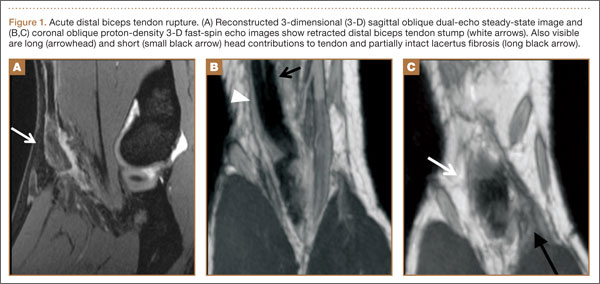
Physical examination revealed distortion of the biceps with a palpable defect in the right elbow consistent with a complete biceps tendon rupture. This was confirmed on MRI, which showed avulsion of the distal biceps tendon from its insertion on the radius. There was 4 cm of proximal retraction of the tendon, which was kept at the level of the joint line by a partially intact lacertus fibrosis (Figure 1).
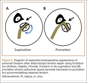
As the patient was physically active, operative treatment was chosen with the expectation of restoration to full function and strength. Six days after injury, surgery was performed using a 1-incision anterior approach with an Endobutton technique, as first described by Bain and colleagues6 and subsequently detailed by other authors.7 The diameter of the distal biceps tendon after attachment to the Endobutton (Arthrex, Naples, Florida) was measured, and a corresponding 7-mm unicortical tunnel was drilled into the radial tuberosity. During surgery, there was full range of motion (ROM) at the elbow and forearm. Before closure, the wound was copiously irrigated to minimize the potential of HO. In our practice, we do not routinely administer prophylactic anti-inflammatory drugs to low-risk patients because of the theoretical risks for delayed tendon–bone healing8 and inferior healing strength.9 The theoretical, expected postoperative appearance is illustrated in Figure 2.
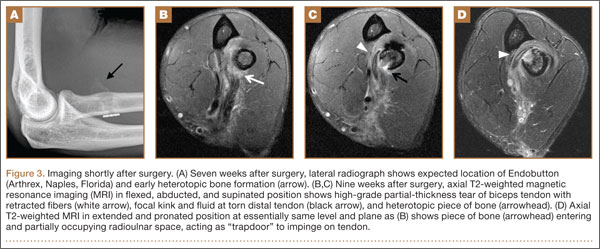
For 7 days after surgery, the patient wore a posterior elbow splint in a flexed, supinated position. Afterward, rehabilitation initially consisted of passive ROM progressing to active ROM at postoperative week 4. Pronation was slow to return, but essentially full ROM was regained by 7 weeks after surgery. Seven weeks after surgery, a radiograph showed a small amount of HO near the radial tuberosity (Figure 3A). However, the patient was clinically progressing well, and by 9 weeks was comfortably performing slow, controlled arm curls with a 10-lb weight. Despite the clinical improvements, MRI 9 weeks after surgery showed high-grade partial-thickness retearing of the distal biceps tendon without significant retraction. With dynamic MRI, it was evident that the focus of HO near but external to the distal tendon entered the radioulnar space on pronation (Figures 3B–3D). On axial images of the center of the cortical tunnel, the short-axis diameter of the heterotopic bone measured 2.5 mm, and the bone clearly was occupying part of the radioulnar space during pronation. As the patient was not having pain and was increasing in strength, the clinical team resumed rehabilitation, albeit at a gentler pace.
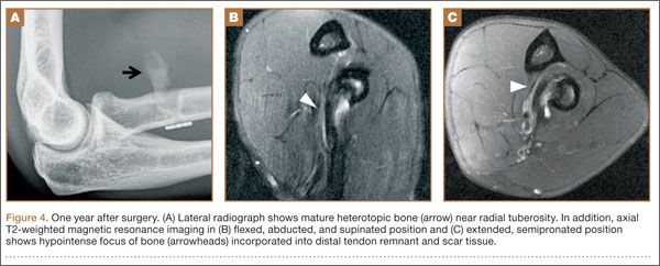
By 1-year follow-up, the patient had returned to preinjury activity levels, which included rock climbing and weightlifting without pain or loss of strength. One year after surgery, radiographs and MRI showed maturation of heterotopic bone, which was incorporated with scar tissue along the remodeled distal biceps tendon remnant (Figures 4A-4C).
Discussion
Distal biceps tendon ruptures historically have been considered relatively rare injuries. Postrepair complications are uncommon but well known. HO has been described with all distal biceps tendon repair techniques, but rates vary depending on follow-up method. Given the data reported, HO is thought to have a higher incidence with the 2-incision technique than with the 1-incision technique.10 The literature includes fewer reports of HO with the Endobutton technique11,12 than with the suture anchor technique.3 Incidence of HO after distal biceps tendon repair has been reported to be as high as 50%, with Marnitz and colleagues5 suggesting that its presence does not necessarily affect clinical outcome. This was confirmed in our patient’s case.
A much rarer complication of repair is rerupture, which can be asymptomatic or symptomatic.5 The most common failure site, discovered during surgery, is the fixation site.2,13 The true incidence of rerupture is unknown, as MRI typically is not obtained for asymptomatic patients. However, Marnitz and colleagues5 recently found increased intratendinous signal and thickness of repaired tendons in the majority of intact postoperative cases and no significant correlation between any MRI features, including tendon rerupture, and clinical measures. This was confirmed in our patient’s case, in which the MRI-based diagnosis of partial retear was not correlated with adverse clinical outcome at 1-year follow-up. Marnitz and colleagues5 hypothesized that the increased thickness of the repaired tendon would predispose the patient to impingement.
Our patient had no demonstrable loss of motion during surgery. However, postoperative dynamic MRI clearly showed insufficient room in the pronated radioulnar space for both heterotopic bone and repaired biceps tendon. It is possible that a space-occupying peritendinous hematoma or HO soon after surgery caused early loss of pronation. In a study of 10 volunteers, mean radioulnar distance was 4.0 mm (range, 2.1-6.0 mm) at its minimum in pronation.14 We used the same technique to measure our patient’s radioulnar space in active semipronation: 7 mm. This diameter was the same as that of the distal biceps tendon during surgery (Figure 3D). Had our patient been in maximum pronation during imaging, we would have expected a further decrease in radioulnar distance. Given the insufficient room in this case, it is possible that, during the attempt to regain full pronation, attritional wear of the repaired biceps tendon occurred with a corresponding maturation of the focus of heterotopic bone. Supporting this theory is the patient’s lack of history of traumatic loading, which would have suggested tensile failure of the repair. By 1-year follow-up, scar-tissue maturation and remodeling had occurred, and there was sufficient overall biomechanical strength to withstand return to normal activity.
The literature includes multiple reports of in vitro biomechanical studies of various types of distal biceps tendon fixation,15-17 and multiple authors have demonstrated the superior pullout strength of cortical fixation buttons,18,19 such as the Endobutton. It is important to note that all biomechanical tests are performed in cadaveric specimens and are therefore likely applicable only at time zero, after in vivo repair. In part stemming from the results of these cadaveric biomechanical tests, earlier and more aggressive rehabilitation protocols have been developed with the assumption that time zero is the weakest point.20 If in fact the native repaired biceps tendon is retorn and remodeled, there will exist a nadir in strength because of the high concentration of biomechanically inferior type III collagen in scar tissue (as opposed to the very strong type I collagen in native tendons).21 In the absence of complete rerupture, biomechanical strength would continue to improve during scar maturation and continued healing, leading to the typical excellent clinical result, as seen in our case.
This case report illustrates the dynamic MRI appearance of a small focus of HO after distal biceps tendon repair and adds to the time-zero cadaveric data of distal biceps tendon repair. The small focus of HO near the repaired distal tendon may have caused tendon impingement in pronation because of its space-occupying nature and possible attritional tendon wear. A gentler rehabilitation protocol for this pattern of HO, during a period in which biomechanically inferior scar tissue is maturing, may be warranted. Despite the high rates of clinical success with distal biceps tendon repair, there is lack of agreement between ex vivo cadaveric studies and the in vivo scenario. A prospective study involving a larger series of patients with postoperative dynamic MRI examinations would be useful to better understand the true in vivo course of distal biceps tendon repair.
1. Cohen MS. Complications of distal biceps tendon repairs. Sports Med Arthrosc. 2008;16(3):148-153.
2. Bisson L, Moyer M, Lanighan K, Marzo J. Complications associated with repair of a distal biceps rupture using the modified two-incision technique. J Shoulder Elbow Surg. 2008;17(1 suppl):67S-71S.
3. Gallinet D, Dietsch E, Barbier-Brion B, Lerais JM, Obert L. Suture anchor reinsertion of distal biceps rupture: clinical results and radiological assessment of tendon healing. Orthop Traumatol Surg Res. 2011;97(3):252-259.
4. Schmidt CC, Diaz VA, Weir DM, Latona CR, Miller MC. Repaired distal biceps magnetic resonance imaging anatomy compared with outcome. J Shoulder Elbow Surg. 2012;21(12):1623-1631.
5. Marnitz T, Spiegel D, Hug K, et al. MR imaging findings in flexed abducted supinated (FABS) position and clinical presentation following refixation of distal biceps tendon rupture using bioabsorbable suture anchors. Rofo. 2012;184(5):432-436.
6. Bain GI, Prem H, Heptinstall RJ, Verhellen R, Paix D. Repair of distal biceps tendon rupture: a new technique using the Endobutton. J Shoulder Elbow Surg. 2000;9(2):120-126.
7. King J, Bollier M. Repair of distal biceps tendon ruptures using the Endobutton. J Am Acad Orthop Surg. 2008;16(8):490-494.
8. Cohen DB, Kawamura S, Ehteshami JR, Rodeo SA. Indomethacin and celecoxib impair rotator cuff tendon-to-bone healing. Am J Sports Med. 2006;34(3):362-369.
9. Ferry ST, Dahners LE, Afshari HM, Weinhold PS. The effects of common anti-inflammatory drugs on the healing rat patellar tendon. Am J Sports Med. 2007;35(8):1326-1333.
10. Miyamoto RG, Elser F, Millett PJ. Distal biceps tendon injuries. J Bone Joint Surg Am. 2010;92(11):2128-2138.
11. Dillon MT, Lepore DJ. Heterotopic ossification after single-incision distal biceps tendon repair with an Endobutton. J Surg Orthop Adv. 2011;20(3):198-201.
12. Peeters T, Ching-Soon NG, Jansen N, Sneyers C, Declercq G, Verstreken F. Functional outcome after repair of distal biceps tendon ruptures using the Endobutton technique. J Shoulder Elbow Surg. 2009;18(2):283-287.
13. Katolik LI, Fernandez J, Cohen MS. Acute failure of distal biceps reconstruction: a case report. J Shoulder Elbow Surg. 2007;16(5):e10-e12.
14. Seiler JG 3rd, Parker LM, Chamberland PD, Sherbourne GM, Carpenter WA. The distal biceps tendon. Two potential mechanisms involved in its rupture: arterial supply and mechanical impingement. J Shoulder Elbow Surg. 1995;4(3):149-156.
15. Siebenlist S, Lenich A, Buchholz A, et al. Biomechanical in vitro validation of intramedullary cortical button fixation for distal biceps tendon repair: a new technique. Am J Sports Med. 2011;39(8):1762-1768.
16. Pereira DS, Kvitne RS, Liang M, Giacobetti FB, Ebramzadeh E. Surgical repair of distal biceps tendon ruptures: a biomechanical comparison of two techniques. Am J Sports Med. 2002;30(3):432-436.
17. Lemos SE, Ebramzedeh E, Kvitne RS. A new technique: in vitro suture anchor fixation has superior yield strength to bone tunnel fixation for distal biceps tendon repair. Am J Sports Med. 2004;32(2):406-410.
18. Kettler M, Lunger J, Kuhn V, Mutschler W, Tingart MJ. Failure strengths in distal biceps tendon repair. Am J Sports Med. 2007;35(9):1544-1548.
19. Mazzocca AD, Burton KJ, Romeo AA, Santangelo S, Adams DA, Arciero RA. Biomechanical evaluation of 4 techniques of distal biceps brachii tendon repair. Am J Sports Med. 2007;35(2):252-258.
20. Spencer EE Jr, Tisdale A, Kostka K, Ivy RE. Is therapy necessary after distal biceps tendon repair? Hand (N Y). 2008;3(4):316-319.
21. Maffulli N, Ewen SWB, Waterston SW, Reaper J, Barrass V. Tenocytes from ruptured and tendinopathic Achilles tendons produce greater quantities of type III collagen than tenocytes from normal Achilles tendons. Am J Sports Med. 2000;28(4):499-505.
Retearing after repair of the distal biceps tendon is rare.1 Heterotopic ossification (HO) is also considered uncommon, though reported rates in the literature vary widely, depending on repair and follow-up methods.1-3
In this article, we report a case of ruptured distal biceps tendon repaired with a 1-incision Endobutton technique with longitudinal clinical and imaging follow-up, and we discuss the potential biomechanical and rehabilitative implications of clinically occult retearing after repair.
This case is unique in that the patient was a physician who procured multiple magnetic resonance imaging (MRI) examinations during the postoperative period and again at 1-year follow-up. We witnessed formation of a small focus of HO, which entered and significantly narrowed the radioulnar space on forearm pronation on dynamic MRI. There was no obvious clinical evidence for retearing; high-grade partial-thickness tendon retearing was diagnosed on MRI. This prompted a gentler rehabilitation protocol. Subsequent scar formation and tendon remodeling allowed the patient to return to full activity by 1-year follow-up, confirming recent reports that intrasubstance signal abnormalities4 and even rerupture on MRI are not correlated with symptoms.5 The patient provided written informed consent for print and electronic publication of this case report.
Case Report
A healthy right-hand–dominant 32-year-old man was rock climbing when he heard a pop and felt sudden weakness in his right elbow. The injury occurred during eccentric contraction, while he was climbing a 45° overhanging wall with his right elbow fully extended and forearm maximally pronated. Immediately after injury, he noticed obvious deformity in the right arm. Before this incident, there was no history of elbow symptoms or any medication use.
Physical examination revealed distortion of the biceps with a palpable defect in the right elbow consistent with a complete biceps tendon rupture. This was confirmed on MRI, which showed avulsion of the distal biceps tendon from its insertion on the radius. There was 4 cm of proximal retraction of the tendon, which was kept at the level of the joint line by a partially intact lacertus fibrosis (Figure 1).
As the patient was physically active, operative treatment was chosen with the expectation of restoration to full function and strength. Six days after injury, surgery was performed using a 1-incision anterior approach with an Endobutton technique, as first described by Bain and colleagues6 and subsequently detailed by other authors.7 The diameter of the distal biceps tendon after attachment to the Endobutton (Arthrex, Naples, Florida) was measured, and a corresponding 7-mm unicortical tunnel was drilled into the radial tuberosity. During surgery, there was full range of motion (ROM) at the elbow and forearm. Before closure, the wound was copiously irrigated to minimize the potential of HO. In our practice, we do not routinely administer prophylactic anti-inflammatory drugs to low-risk patients because of the theoretical risks for delayed tendon–bone healing8 and inferior healing strength.9 The theoretical, expected postoperative appearance is illustrated in Figure 2.
For 7 days after surgery, the patient wore a posterior elbow splint in a flexed, supinated position. Afterward, rehabilitation initially consisted of passive ROM progressing to active ROM at postoperative week 4. Pronation was slow to return, but essentially full ROM was regained by 7 weeks after surgery. Seven weeks after surgery, a radiograph showed a small amount of HO near the radial tuberosity (Figure 3A). However, the patient was clinically progressing well, and by 9 weeks was comfortably performing slow, controlled arm curls with a 10-lb weight. Despite the clinical improvements, MRI 9 weeks after surgery showed high-grade partial-thickness retearing of the distal biceps tendon without significant retraction. With dynamic MRI, it was evident that the focus of HO near but external to the distal tendon entered the radioulnar space on pronation (Figures 3B–3D). On axial images of the center of the cortical tunnel, the short-axis diameter of the heterotopic bone measured 2.5 mm, and the bone clearly was occupying part of the radioulnar space during pronation. As the patient was not having pain and was increasing in strength, the clinical team resumed rehabilitation, albeit at a gentler pace.
By 1-year follow-up, the patient had returned to preinjury activity levels, which included rock climbing and weightlifting without pain or loss of strength. One year after surgery, radiographs and MRI showed maturation of heterotopic bone, which was incorporated with scar tissue along the remodeled distal biceps tendon remnant (Figures 4A-4C).
Discussion
Distal biceps tendon ruptures historically have been considered relatively rare injuries. Postrepair complications are uncommon but well known. HO has been described with all distal biceps tendon repair techniques, but rates vary depending on follow-up method. Given the data reported, HO is thought to have a higher incidence with the 2-incision technique than with the 1-incision technique.10 The literature includes fewer reports of HO with the Endobutton technique11,12 than with the suture anchor technique.3 Incidence of HO after distal biceps tendon repair has been reported to be as high as 50%, with Marnitz and colleagues5 suggesting that its presence does not necessarily affect clinical outcome. This was confirmed in our patient’s case.
A much rarer complication of repair is rerupture, which can be asymptomatic or symptomatic.5 The most common failure site, discovered during surgery, is the fixation site.2,13 The true incidence of rerupture is unknown, as MRI typically is not obtained for asymptomatic patients. However, Marnitz and colleagues5 recently found increased intratendinous signal and thickness of repaired tendons in the majority of intact postoperative cases and no significant correlation between any MRI features, including tendon rerupture, and clinical measures. This was confirmed in our patient’s case, in which the MRI-based diagnosis of partial retear was not correlated with adverse clinical outcome at 1-year follow-up. Marnitz and colleagues5 hypothesized that the increased thickness of the repaired tendon would predispose the patient to impingement.
Our patient had no demonstrable loss of motion during surgery. However, postoperative dynamic MRI clearly showed insufficient room in the pronated radioulnar space for both heterotopic bone and repaired biceps tendon. It is possible that a space-occupying peritendinous hematoma or HO soon after surgery caused early loss of pronation. In a study of 10 volunteers, mean radioulnar distance was 4.0 mm (range, 2.1-6.0 mm) at its minimum in pronation.14 We used the same technique to measure our patient’s radioulnar space in active semipronation: 7 mm. This diameter was the same as that of the distal biceps tendon during surgery (Figure 3D). Had our patient been in maximum pronation during imaging, we would have expected a further decrease in radioulnar distance. Given the insufficient room in this case, it is possible that, during the attempt to regain full pronation, attritional wear of the repaired biceps tendon occurred with a corresponding maturation of the focus of heterotopic bone. Supporting this theory is the patient’s lack of history of traumatic loading, which would have suggested tensile failure of the repair. By 1-year follow-up, scar-tissue maturation and remodeling had occurred, and there was sufficient overall biomechanical strength to withstand return to normal activity.
The literature includes multiple reports of in vitro biomechanical studies of various types of distal biceps tendon fixation,15-17 and multiple authors have demonstrated the superior pullout strength of cortical fixation buttons,18,19 such as the Endobutton. It is important to note that all biomechanical tests are performed in cadaveric specimens and are therefore likely applicable only at time zero, after in vivo repair. In part stemming from the results of these cadaveric biomechanical tests, earlier and more aggressive rehabilitation protocols have been developed with the assumption that time zero is the weakest point.20 If in fact the native repaired biceps tendon is retorn and remodeled, there will exist a nadir in strength because of the high concentration of biomechanically inferior type III collagen in scar tissue (as opposed to the very strong type I collagen in native tendons).21 In the absence of complete rerupture, biomechanical strength would continue to improve during scar maturation and continued healing, leading to the typical excellent clinical result, as seen in our case.
This case report illustrates the dynamic MRI appearance of a small focus of HO after distal biceps tendon repair and adds to the time-zero cadaveric data of distal biceps tendon repair. The small focus of HO near the repaired distal tendon may have caused tendon impingement in pronation because of its space-occupying nature and possible attritional tendon wear. A gentler rehabilitation protocol for this pattern of HO, during a period in which biomechanically inferior scar tissue is maturing, may be warranted. Despite the high rates of clinical success with distal biceps tendon repair, there is lack of agreement between ex vivo cadaveric studies and the in vivo scenario. A prospective study involving a larger series of patients with postoperative dynamic MRI examinations would be useful to better understand the true in vivo course of distal biceps tendon repair.
1. Cohen MS. Complications of distal biceps tendon repairs. Sports Med Arthrosc. 2008;16(3):148-153.
2. Bisson L, Moyer M, Lanighan K, Marzo J. Complications associated with repair of a distal biceps rupture using the modified two-incision technique. J Shoulder Elbow Surg. 2008;17(1 suppl):67S-71S.
3. Gallinet D, Dietsch E, Barbier-Brion B, Lerais JM, Obert L. Suture anchor reinsertion of distal biceps rupture: clinical results and radiological assessment of tendon healing. Orthop Traumatol Surg Res. 2011;97(3):252-259.
4. Schmidt CC, Diaz VA, Weir DM, Latona CR, Miller MC. Repaired distal biceps magnetic resonance imaging anatomy compared with outcome. J Shoulder Elbow Surg. 2012;21(12):1623-1631.
5. Marnitz T, Spiegel D, Hug K, et al. MR imaging findings in flexed abducted supinated (FABS) position and clinical presentation following refixation of distal biceps tendon rupture using bioabsorbable suture anchors. Rofo. 2012;184(5):432-436.
6. Bain GI, Prem H, Heptinstall RJ, Verhellen R, Paix D. Repair of distal biceps tendon rupture: a new technique using the Endobutton. J Shoulder Elbow Surg. 2000;9(2):120-126.
7. King J, Bollier M. Repair of distal biceps tendon ruptures using the Endobutton. J Am Acad Orthop Surg. 2008;16(8):490-494.
8. Cohen DB, Kawamura S, Ehteshami JR, Rodeo SA. Indomethacin and celecoxib impair rotator cuff tendon-to-bone healing. Am J Sports Med. 2006;34(3):362-369.
9. Ferry ST, Dahners LE, Afshari HM, Weinhold PS. The effects of common anti-inflammatory drugs on the healing rat patellar tendon. Am J Sports Med. 2007;35(8):1326-1333.
10. Miyamoto RG, Elser F, Millett PJ. Distal biceps tendon injuries. J Bone Joint Surg Am. 2010;92(11):2128-2138.
11. Dillon MT, Lepore DJ. Heterotopic ossification after single-incision distal biceps tendon repair with an Endobutton. J Surg Orthop Adv. 2011;20(3):198-201.
12. Peeters T, Ching-Soon NG, Jansen N, Sneyers C, Declercq G, Verstreken F. Functional outcome after repair of distal biceps tendon ruptures using the Endobutton technique. J Shoulder Elbow Surg. 2009;18(2):283-287.
13. Katolik LI, Fernandez J, Cohen MS. Acute failure of distal biceps reconstruction: a case report. J Shoulder Elbow Surg. 2007;16(5):e10-e12.
14. Seiler JG 3rd, Parker LM, Chamberland PD, Sherbourne GM, Carpenter WA. The distal biceps tendon. Two potential mechanisms involved in its rupture: arterial supply and mechanical impingement. J Shoulder Elbow Surg. 1995;4(3):149-156.
15. Siebenlist S, Lenich A, Buchholz A, et al. Biomechanical in vitro validation of intramedullary cortical button fixation for distal biceps tendon repair: a new technique. Am J Sports Med. 2011;39(8):1762-1768.
16. Pereira DS, Kvitne RS, Liang M, Giacobetti FB, Ebramzadeh E. Surgical repair of distal biceps tendon ruptures: a biomechanical comparison of two techniques. Am J Sports Med. 2002;30(3):432-436.
17. Lemos SE, Ebramzedeh E, Kvitne RS. A new technique: in vitro suture anchor fixation has superior yield strength to bone tunnel fixation for distal biceps tendon repair. Am J Sports Med. 2004;32(2):406-410.
18. Kettler M, Lunger J, Kuhn V, Mutschler W, Tingart MJ. Failure strengths in distal biceps tendon repair. Am J Sports Med. 2007;35(9):1544-1548.
19. Mazzocca AD, Burton KJ, Romeo AA, Santangelo S, Adams DA, Arciero RA. Biomechanical evaluation of 4 techniques of distal biceps brachii tendon repair. Am J Sports Med. 2007;35(2):252-258.
20. Spencer EE Jr, Tisdale A, Kostka K, Ivy RE. Is therapy necessary after distal biceps tendon repair? Hand (N Y). 2008;3(4):316-319.
21. Maffulli N, Ewen SWB, Waterston SW, Reaper J, Barrass V. Tenocytes from ruptured and tendinopathic Achilles tendons produce greater quantities of type III collagen than tenocytes from normal Achilles tendons. Am J Sports Med. 2000;28(4):499-505.
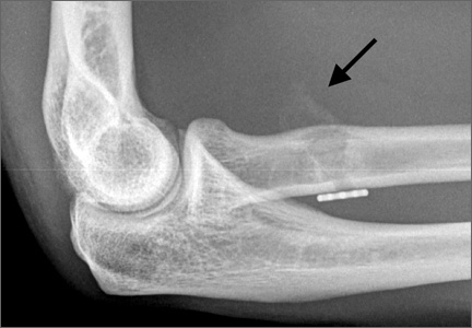
Visualization and Reduction of a Meniscal Capsular Junction Tear in the Knee: An Arthroscopic Surgical Technique
The annual incidence of anterior cruciate ligament (ACL) injury in the general US population is estimated at 1 in 3000, or approximately 100,000 ACL injuries per year.1 The incidence of meniscal injuries after ACL tears ranges from 34% to 92%,2 with peripheral posterior horn tears of the medial meniscus accounting for 40% of the meniscal pathology.3
Although several meniscal tear patterns and their treatments have been described in the literature, posterior medial meniscal capsular junction (MCJ) tears have not been adequately addressed. Thijn4 found the accuracy of routine anterior portal arthroscopy in identifying medial meniscus tears was only 81%. Gillies and Seligson5 found a 25% arthroscopic false-negative rate caused by failure to detect peripheral tears in the posterior horn of the medial meniscus.
We reviewed 781 (517 male, 264 female) patients who underwent ACL reconstruction at our clinic and found a 12.3% incidence of MCJ tear with primary ACL injury and a 23.6% incidence of MCJ tear with revision ACL reconstruction. We believe this is a specific injury pattern. If not looked for during arthroscopy, it can be missed. Whether this tear pattern behaves differently from a posterior medial meniscus tear is yet to be determined.
To address such tear patterns, with or without ACL reconstruction, we use an arthroscopic repair technique that shows direct visualization of the tear and its reduction.
Materials and Methods
The standard anterior medial and lateral arthroscopic portals are established. A 30° scope is placed in the anterior lateral portal, and an arthroscopic shaver is used to débride the ACL remnants, including the footprint and the femoral insertion site. The camera is then adjusted to look straight down. Next, it is placed between the posterior cruciate ligament (PCL) and the medial femoral condyle and advanced toward the posterior capsule. It is then adjusted to view medially (Figure 1). If there is a tear (Figures 2A, 2B), a posterior medial portal (described by Gillquist and colleagues6) is established using an 18-gauge spinal needle for localization followed by a small stab incision through the skin. The spinal needle is left in position to obtain the correct angle for the suture passer (Figure 3). A 70° Hewson suture passer (Smith & Nephew, Memphis, Tennessee) is passed through the posterior medial portal.
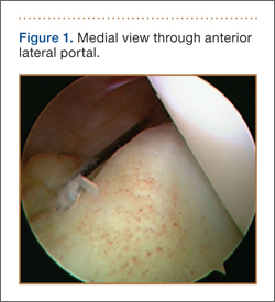
Once inside the joint, the suture passer is passed through the capsule and then through the posterior horn of the meniscus (Figure 4). A loop grasper is used to grab the suture on the end of the passer and then is brought out the posterior medial portal and loaded with a No. 2 MaxBraid suture (Biomet, Warsaw, Indiana) (Figure 5). In some cases, the suture passer’s wire goes out the notch toward the anterior aspect of the knee. If this occurs, the loop grasper can be used to grab this wire from the anterior medial portal and load with the MaxBraid suture.
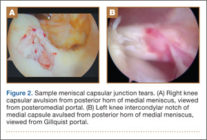
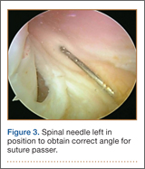
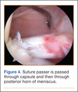
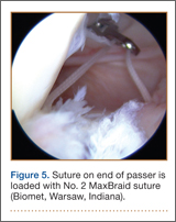
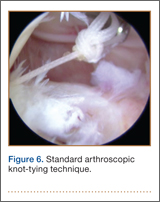
Standard arthroscopic knot-tying techniques are used under direct visualization showing the reduction of the capsule to the meniscus (Figure 6). This is done from the posterior medial portal. The excess suture is cut with an arthroscopic suture cutter in the standard fashion. In the rare case of an intact ACL with this same tear pattern, the same technique can be used. If there is difficulty moving past the intact ACL and PCL, a posterior lateral portal can be used as another accessory portal. The arthroscope can then be placed in the posterior lateral portal, while the posterior medial portal can be used as the working portal. Care must be taken in either technique to avoid soft-tissue bridges.
Discussion
Previous biomechanical studies have shown the meniscus to be important to knee stability. In an ACL-deficient knee, the posterior medial meniscus is important as a secondary stabilizer, and for that reason it is crucial to identify and repair tears there to avoid risking extra force on the ACL graft.7,8 We think an MCJ tear can potentially compromise knee stability as well, so there is a need to examine the posterior aspect of the knee during every knee arthroscopy. However, biomechanical studies must be performed to validate this theory.
To assess whether orthopedists in general are aware of and concerned about MCJ tears, a survey was e-mailed to members of the Arthroscopy Association of North America (AANA) and the American Sports Medicine Fellowship Society (ASMFS). Sixty-seven orthopedic surgeons who perform ACL reconstruction surgeries responded to some or all of the following questions. Nearly half (48%) of the surgeons said they always assess the posteromedial MCJ by placing the camera between the PCL and the medial femoral condyle. Only 25% said MCJ tears should be repaired always, but another 64% said these tears should be repaired sometimes. Thus, 89% responded that at least some MCJ tears should be repaired. Most (88%) said these tears could sometimes or always be a source of chronic pain. Also, 92% said these tears could sometimes or always change the contact pressures in the knee, and 66% said these tears could sometimes or always change the rotational stability of the knee. Finally, 60% said MCJ tears could sometimes or always affect ACL graft failure. These data show a need to determine an appropriate surgical technique that will help treat MCJ tears.
There is a vast amount of literature about the meniscus, but there are few current studies on the specific entity of MCJ tears. We think these tears act similarly to posterior meniscus tears and should be addressed similarly. MCJ tears are easily missed on anterior arthroscopy. In every knee arthroscopy, the posterior aspect of the knee should be checked for these injuries, particularly in ACL-deficient knees. A lesion found within the capsule can be repaired with the technique we have described.
1. Fu FH, Cohen SB. Current Concepts in ACL Reconstruction. Thorofare, NJ: Slack; 2008.
2. Simonian PT, Cole BJ, Bach BR. Sports Injuries of the Knee: Surgical Approaches. New York, NY: Thieme; 2006.
3. Smith JP 3rd, Barrett GR. Medial and lateral meniscal tear patterns in anterior cruciate ligament-deficient knees. A prospective analysis of 575 tears. Am J Sports Med. 2001;29(4):415-419.
4. Thijn CJ. Accuracy of double-contrast arthrography and arthroscopy of the knee joint. Skeletal Radiol. 1982;8(3):187-192.
5. Gillies H, Seligson D. Precision in the diagnosis of meniscal lesions: a comparison of clinical evaluation, arthrography, and arthroscopy. J Bone Joint Surg Am. 1979;61(3):343-346.
6. Gillquist J, Hagberg G, Oretorp N. Arthroscopic examination of the posteromedial compartment of the knee joint. Int Orthop. 1979;3(1):13-18.
7. Levy IM, Torzilli PA, Warren RF. The effect of medial meniscectomy on anterior-posterior motion of the knee. J Bone Joint Surg Am. 1982;64(6):883-888.
8. Allen CR, Wong EK, Livesay GA, Sakane M, Fu FH, Woo SL. Importance of the medial meniscus in the anterior cruciate ligament–deficient knee. J Orthop Res. 2000;18(1):109-115.
The annual incidence of anterior cruciate ligament (ACL) injury in the general US population is estimated at 1 in 3000, or approximately 100,000 ACL injuries per year.1 The incidence of meniscal injuries after ACL tears ranges from 34% to 92%,2 with peripheral posterior horn tears of the medial meniscus accounting for 40% of the meniscal pathology.3
Although several meniscal tear patterns and their treatments have been described in the literature, posterior medial meniscal capsular junction (MCJ) tears have not been adequately addressed. Thijn4 found the accuracy of routine anterior portal arthroscopy in identifying medial meniscus tears was only 81%. Gillies and Seligson5 found a 25% arthroscopic false-negative rate caused by failure to detect peripheral tears in the posterior horn of the medial meniscus.
We reviewed 781 (517 male, 264 female) patients who underwent ACL reconstruction at our clinic and found a 12.3% incidence of MCJ tear with primary ACL injury and a 23.6% incidence of MCJ tear with revision ACL reconstruction. We believe this is a specific injury pattern. If not looked for during arthroscopy, it can be missed. Whether this tear pattern behaves differently from a posterior medial meniscus tear is yet to be determined.
To address such tear patterns, with or without ACL reconstruction, we use an arthroscopic repair technique that shows direct visualization of the tear and its reduction.
Materials and Methods
The standard anterior medial and lateral arthroscopic portals are established. A 30° scope is placed in the anterior lateral portal, and an arthroscopic shaver is used to débride the ACL remnants, including the footprint and the femoral insertion site. The camera is then adjusted to look straight down. Next, it is placed between the posterior cruciate ligament (PCL) and the medial femoral condyle and advanced toward the posterior capsule. It is then adjusted to view medially (Figure 1). If there is a tear (Figures 2A, 2B), a posterior medial portal (described by Gillquist and colleagues6) is established using an 18-gauge spinal needle for localization followed by a small stab incision through the skin. The spinal needle is left in position to obtain the correct angle for the suture passer (Figure 3). A 70° Hewson suture passer (Smith & Nephew, Memphis, Tennessee) is passed through the posterior medial portal.
Once inside the joint, the suture passer is passed through the capsule and then through the posterior horn of the meniscus (Figure 4). A loop grasper is used to grab the suture on the end of the passer and then is brought out the posterior medial portal and loaded with a No. 2 MaxBraid suture (Biomet, Warsaw, Indiana) (Figure 5). In some cases, the suture passer’s wire goes out the notch toward the anterior aspect of the knee. If this occurs, the loop grasper can be used to grab this wire from the anterior medial portal and load with the MaxBraid suture.
Standard arthroscopic knot-tying techniques are used under direct visualization showing the reduction of the capsule to the meniscus (Figure 6). This is done from the posterior medial portal. The excess suture is cut with an arthroscopic suture cutter in the standard fashion. In the rare case of an intact ACL with this same tear pattern, the same technique can be used. If there is difficulty moving past the intact ACL and PCL, a posterior lateral portal can be used as another accessory portal. The arthroscope can then be placed in the posterior lateral portal, while the posterior medial portal can be used as the working portal. Care must be taken in either technique to avoid soft-tissue bridges.
Discussion
Previous biomechanical studies have shown the meniscus to be important to knee stability. In an ACL-deficient knee, the posterior medial meniscus is important as a secondary stabilizer, and for that reason it is crucial to identify and repair tears there to avoid risking extra force on the ACL graft.7,8 We think an MCJ tear can potentially compromise knee stability as well, so there is a need to examine the posterior aspect of the knee during every knee arthroscopy. However, biomechanical studies must be performed to validate this theory.
To assess whether orthopedists in general are aware of and concerned about MCJ tears, a survey was e-mailed to members of the Arthroscopy Association of North America (AANA) and the American Sports Medicine Fellowship Society (ASMFS). Sixty-seven orthopedic surgeons who perform ACL reconstruction surgeries responded to some or all of the following questions. Nearly half (48%) of the surgeons said they always assess the posteromedial MCJ by placing the camera between the PCL and the medial femoral condyle. Only 25% said MCJ tears should be repaired always, but another 64% said these tears should be repaired sometimes. Thus, 89% responded that at least some MCJ tears should be repaired. Most (88%) said these tears could sometimes or always be a source of chronic pain. Also, 92% said these tears could sometimes or always change the contact pressures in the knee, and 66% said these tears could sometimes or always change the rotational stability of the knee. Finally, 60% said MCJ tears could sometimes or always affect ACL graft failure. These data show a need to determine an appropriate surgical technique that will help treat MCJ tears.
There is a vast amount of literature about the meniscus, but there are few current studies on the specific entity of MCJ tears. We think these tears act similarly to posterior meniscus tears and should be addressed similarly. MCJ tears are easily missed on anterior arthroscopy. In every knee arthroscopy, the posterior aspect of the knee should be checked for these injuries, particularly in ACL-deficient knees. A lesion found within the capsule can be repaired with the technique we have described.
1. Fu FH, Cohen SB. Current Concepts in ACL Reconstruction. Thorofare, NJ: Slack; 2008.
2. Simonian PT, Cole BJ, Bach BR. Sports Injuries of the Knee: Surgical Approaches. New York, NY: Thieme; 2006.
3. Smith JP 3rd, Barrett GR. Medial and lateral meniscal tear patterns in anterior cruciate ligament-deficient knees. A prospective analysis of 575 tears. Am J Sports Med. 2001;29(4):415-419.
4. Thijn CJ. Accuracy of double-contrast arthrography and arthroscopy of the knee joint. Skeletal Radiol. 1982;8(3):187-192.
5. Gillies H, Seligson D. Precision in the diagnosis of meniscal lesions: a comparison of clinical evaluation, arthrography, and arthroscopy. J Bone Joint Surg Am. 1979;61(3):343-346.
6. Gillquist J, Hagberg G, Oretorp N. Arthroscopic examination of the posteromedial compartment of the knee joint. Int Orthop. 1979;3(1):13-18.
7. Levy IM, Torzilli PA, Warren RF. The effect of medial meniscectomy on anterior-posterior motion of the knee. J Bone Joint Surg Am. 1982;64(6):883-888.
8. Allen CR, Wong EK, Livesay GA, Sakane M, Fu FH, Woo SL. Importance of the medial meniscus in the anterior cruciate ligament–deficient knee. J Orthop Res. 2000;18(1):109-115.
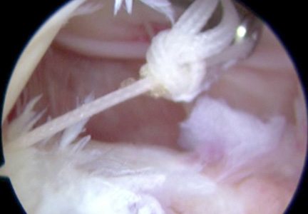
Conversion of Cephalomedullary Nail Fixation to Hip Arthroplasty: Technical Points and Pitfalls
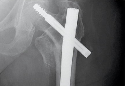
Big Data: The Paradigm Shift Needed to Revolutionize Musculoskeletal Clinical Research
One year ago, we wrote an editorial in The American Journal of Orthopedics on missing data.1 This year, data is once again the focus of our editorial but from a
different perspective. Rather than focus on the problems of incomplete data, we want to talk about the possibilities of collecting all data through advanced technology, a phenomenon better known as “Big Data.”
New Technology
The factors driving Big Data’s ascendency are the digitalization of useful data, increased means to gather digitalized data, and cheaper analytic power.2 Computer behemoth IBM claims that 90% of the data in the world today has been created in the last 2 years alone.3 Big Data is not just an industry buzzword; it is already an industry in itself. Revenue from Big Data reached $18 billion in 2013 and is predicted to rise to $50 billion in the next 5 years.4 While it is easy to see how Internet companies like Amazon can both collect and use all of the data they receive from customers (to suggest their next purchase, for example), it might be less easy to see how Big Data concepts can be applied to clinical research.
Health Care
Electronic data records are propelling the development of pools of information in health care. Almost half of all hospitals in the United States are participating in health information exchanges (HIEs).5 When these sources of data pools are integrated, the information collected can be used in a powerful way. For example, the health maintenance organization Kaiser Permanente uses a new computer system that drives data exchange between medical facilities. Patient benefits include improved outcomes of cardiovascular disease, and an estimated $1 billion has been saved due to reduced office visits and laboratory tests.5
Contemporary Studies
Let’s quickly consider how we currently conduct clinical studies. Because we do not usually collect data from the entire population, contemporary clinical studies offer only a snapshot of a subsection of patients. The results from this sample are then usually extrapolated to the general population. This was fine when there were insurmountable technological and logistical issues. So instead of trying to
collect data from everyone in the population of interest, we select a sample of patients and expend our energy on controlling for the suboptimal methods we currently employ, techniques which are the best ones available to us.
What are the consequences of all this? Those of us in clinical research are usually very concerned about dealing with confounding factors: selection bias, adjusting for missing data, controlling for errors, and so on. We can also see how imprecise our current methods are by how often a scientific manuscript ends with a call for larger-scale research. Indeed, a scientific research paper that does not list the study’s limitations is often regarded with suspicion, a telling indictment of the problems we expect to encounter in clinical research.
So what has historically been the best current solution to overcome these challenges? A meta-analysis of randomized controlled trials sits atop the evidence pyramid as being the best level of evidence. However, even the use of meta-analyses can be problematic. One group of researchers found that in 2005 and 2008, respectively, 18% and 30% of orthopedic meta-analyses had major to extensive flaws in their methodology.6 Indeed, implicit in the use of a meta-analysis is a criticism that our current studies with their limited sample sizes do not tell the whole story.
Paradigm Shift
We are in the middle of a paradigm shift in the way we can collect and analyze data. Our focus until now has been on identifying a causal relationship in our studies. New technology which allows for large-scale data collection and analysis means that we can now collect ALL patient data, in other words N = all. When you can collect all data, the why (causality) something is happening becomes less
important than the what (correlation) is happening.7 Studies will therefore begin to focus on effectiveness in the real world as opposed to measurements taken under the ideal (or nearly ideal) conditions of efficacy.
All of this is going to have implications, the greatest of which is the change in mindset that we are going to have to go through. How we conduct our studies and what their focus is will both change and expand. For example, the Mini-Sentinel project uses preexisting electronic health care data from multiple sources to monitor the safety of medical products that are regulated by the US Food and
Drug Administration (FDA). This FDA-sponsored initiative, which only began in 2008, had already collected data on 178 million individuals by July 2014.8
Since we cannot ignore Big Data, we must do what we can to ensure that its potential is harnessed to reduce costs and improve patient outcomes. Given the potential of using electronic clinical data, it is also necessary to strike a note of caution. We have to keep uppermost in mind that new technologies like Big Data can unsettle a lot of people. A central tenet of clinical research is that patient data belong to the patient. Robust and transparent processes need to be developed to ensure that patients do not feel compromised in any way by their data being used in such new and widespread methods. The need to rethink and implement safeguards is already being addressed. For example, the university-associated Regenstrief Institute does not pass along even deidentified data to their Big Data industry partner.9
However, we need to also be cognizant of the fact that society is changing in the way people use and regard their own information. Patient-reported data is already being shared among patients online, for both common and rare diseases. The data are also richer and can go beyond the usual outcomes that are recorded to give a bigger picture, eg, why patients are not adhering to treatment regimens.10
In summary, it is our earnest belief that if the health care industry can embrace the concept of Big Data and utilize it properly, our patients and medical practices will be all the better for it.
References
1. Helfet DL, Hanson BP, De Faoite D. Publish or perish; but what, when,
and how? Am J Orthop. 2013;42(9):399-400.
2. Nash DB. Harnessing the power of big data in healthcare. Am Health
Drug Benefits. 2014;7(2):69-70.
3. What is big data? IBM website. http://www-01.ibm.com/software/data/
bigdata/what-is-big-data.html. Accessed July 22, 2014.
4. Upbin B. Visualizing the big data industrial complex. Forbes website.
http://www.forbes.com/sites/bruceupbin/2013/08/30/visualizing-thebig-
data-industrial-complex-infographic/. Published August 30, 2013. Accessed July 22, 2014.
5. Kayyali B, Knott D, Van Kuiken S. The big-data revolution in US health
care: accelerating value and innovation. McKinsey & Company website.
http://www.mckinsey.com/insights/health_systems_and_services/
the_big-data_revolution_in_us_health_care. Published January 2013.
Accessed July 22, 2014.
6. Dijkman BG, Abouali JA, Kooistra BW, et al. Twenty years of meta-analyses
in orthopaedic surgery: has quality kept up with quantity? J Bone Joint Surg Am. 2010;92(1):48-57.
7. Cukier K, Mayer-Schonberger V. Big Data: A Revolution That Will Transform
How We Live, Work, and Think. New York, NY: Eamon Dolan/Houghton Mifflin Harcourt; 2013.
8. Mini-Sentinel distributed data “at a glance.” Mini-Sentinel website.
http://www.mini-sentinel.org/about_us/MSDD_At-a-Glance.aspx. Accessed July 22, 2014.
9. Jain SH, Rosenblatt M, Duke J. Is big data the new frontier for academic-
industry collaboration? JAMA. 2014;311(21):2171-2172.
10. Okun S, McGraw D, Stang P, et al. Making the case for continuous
learning from routinely collected data. Institute of Medicine website.
http://www.iom.edu/Global/Perspectives/2013/~/media/Files/
Perspectives-Files/2013/Discussion-Papers/VSRT-MakingtheCase.pdf. Published April 15, 2013. Accessed July 22, 2014.