User login
GoPro Hero 3 Latarjet Procedure
Coracoid harvest for transfer during Latarjet procedure performed and filmed by Dr. Jobin using GoPro Hero 3.
To read the authors' full article "5 Points on Using Wearable Technology to Record Surgical Videos," click here.
The video associated with this article is no longer available on this site. Please view all of our videos on the MDedge YouTube channel
Using Wearable Technology to Record Surgical Videos
Safe and efficient advanced surgical skill training is of tremendous importance. With the recent increase in Internet use for medical education, there has been a concomitant increase in video recording of surgical procedures and techniques. Surgical recordings have been used in a variety of ways—as live webcasts for remote participants, as “coaching” opportunities for surgeons evaluating their own performance in the operating room, and even as informational resources for patients about to undergo the same surgery.
Surgical multimedia is being delivered through several different outlets. Many academic conferences and meetings showcase videos of different procedures, and several subspecialty societies (eg, Arthroscopy Association of North America) house archives of technical videos for viewing by members. In addition, the VuMedi website offers videos and allows members to comment on them and interact with the videographers. Surgeons are even posting technique videos on YouTube and other public websites.
A large proportion of surgical multimedia is recorded with conventional high-definition video cameras.1 Besides being able to experience a case at any time and from outside the operating room, the audience can watch from numerous vantage points, angles, and zoom levels. Also, surgeons’ narration can be valuable in helping the audience follow along with the case.
Recording surgical multimedia historically required tight coordination and precise planning by surgeon and videographer. However, innovations in wearable technology now allow surgeons to literally wear video cameras and record procedures as they perform them, in real time—to act as both surgeon and videographer.
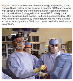
Two such products are Google Glass (Google, Mountain View, California) and GoPro Hero (GoPro, San Mateo, California), both of which allow surgeons to record exactly what they see during procedures (Figure 1). Using a wearable technology for surgical multimedia creation requires a deep familiarity with its capabilities and limitations. In this article, we summarize these products’ similarities and differences and provide a technical overview for using wearable technologies in surgical multimedia creation.
1. Choosing a device
When purchasing either wearable device, several factors must be considered, including budget, possible uses outside the operating room, and possible limitations of the technology (Table 1). At this time, Google Glass is significantly more expensive than GoPro Hero. The Google Glass base unit costs $1500, and the GoPro Hero 3 model costs approximately $200 (higher-priced Hero models are available). Both devices require accessories (eg, portable battery unit, dedicated hard drive).
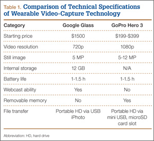
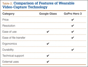
Device capabilities must also be considered (Table 2). Google Glass consists of both hardware and software. Users can record what is seen and heard through the lens and then use apps to create text and e-mail portals to online gaming, social media, and even golf-course GPS. The app market for Google Glass is nascent but undoubtedly will increase in volume and scope as more users adopt the technology (Google Glass comes with both Bluetooth and Wi-Fi and can function tethered through a smartphone). GoPro is mainly a hardware unit that can record in various settings (it is popular with athletes who want to capture and broadcast their participation in action sports). Newer GoPro Hero versions offer Wi-Fi, which allows streaming of video content to a smartphone or tablet through an app. Having clearly defined goals for a device—as they pertain to use outside the operating room, such as outdoor activities and underwater recording—may help the surgeon decide which product is more suitable. Last, it is important to consider limitations. Google Glass resolution is 720p (1280×720) for video and 5 MP for still images, and GoPro resolution can reach 1080p (1920×1080) for video and 5 MP for stills.
Both devices require purchase of accessories. An external USB battery pack is useful for both devices, as is a password-encrypted hard drive for media storage. Lenswear does not come with the base version of Google Glass and is purchased separately from the company. GoPro users buy micro SD cards (~$50 per 64-GB high-speed transfer card) for storage on the device and may buy lithium-ion batteries as an alternative to the external USB battery pack.
Author Update
In January 2015, Google announced that it was temporarily suspending its “Explorer” program, which allowed individual users to buy and test the device for personal use. However, Google is continuing its development of Glass with health care technology, among other areas of growth and development.2,3
2. Recording a successful surgical video
Unlike a camcorder, which typically is set on a tripod for conventional video recording of surgery, Google Glass and GoPro are intricately linked to the operator. Surgeons must be constantly aware of where they are during surgery and try not to let anything obstruct the camera’s view.
Before starting a case, the surgeon using either device must ensure that its battery is fully charged, as a full charge typically supports 1 hour of continuous recording (the Google Glass battery is a lithium-ion 670-mAh internal unit). A full charge should be enough to capture a short case. Newer GoPro models, with a battery listed at 1050 mAh, provide 1 to 2 hours of recording. When more than 1 hour is needed, an external USB battery pack can be used. This pack allows the device to remain plugged in throughout the case (the pack is kept in the surgeon’s back pocket). We recommend having an external battery pack that is at least 10,000 mAh (~$30 online retail), which easily provides 3+ hours of recording. Unfortunately, this arrangement can be cumbersome. Alternatively, with GoPro, additional batteries may be purchased, but the user needs to dismount the device in order to swap them in (may be difficult during surgery). With both units, partitioning a video into shorter segments conserves battery power and minimizes the risk of file corruption, which may occur if the battery dies or the device overheats.
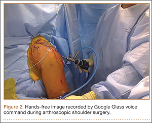
Google Glass users can bypass manual operation of the device by giving it voice commands (eg, start video, take still image). The exception is for recording video for more than 10 seconds (current default setting). Unfortunately, the surgeon must touch the device to start this recording, which means using extra gloves to preserve operating field sterility. Still images can be made through a combination of voice and head gestures and without manual intervention (Figure 2). Last, users must ensure that the device is not actively connected through Bluetooth to a mobile phone, as incoming calls, text messages, and e-mails may disrupt active recording and become a distraction. The connection can be deactivated by disabling Bluetooth on the host smartphone or by placing the phone into airplane mode and turning off Wi-Fi.
Google Glass users can see what is being recorded through the viewfinder prism, whereas GoPro requires precise framing of the video before recording. Framing is done by grossly aiming the device in the desired direction. However, there is no way to ensure exact aim during recording. If at any point during a case there is slight repositioning of the GoPro, there is a risk of recording the case out of the center of view. An important advantage to newer GoPro versions is the ability to control the device through a wireless remote that can be placed under the surgeon’s gown. The remote can be used to pause and resume recording, without changing gloves, as is done with Google Glass. Last, because the minimum viewing distance from the surgical field is usually 18 inches or more, typically there is no loss of focus or blurring of the image from short-distance recording on either device.
3. File management and playback
Before using wearable technology in the operating room, surgeons must become aware of its limitations with respect to file storage and playback. Google Glass has a usable memory of about 12 GB (1 hour of video may require 1.5-2.0 GB). Conversely, GoPro’s capacity is defined by the micro SD card used. Therefore, the Google Glass hard drive must be regularly maintained well before being brought into the operating room, whereas recording can be extended (with respect to memory) for the GoPro if the media card is large enough.
Both devices allow for wired file transfer, which may be done with Windows Explorer (PC) or iPhoto (Macintosh). However, Google Glass also allows for wireless transfer, through portable storage supported by Google. Although this type of file transfer may be convenient for short, everyday clips made outside the operating room, it is prohibitive for surgical media, mainly because of patient privacy concerns. With wireless transfer to a nonsecure cloud platform, there is a risk of breach of patient confidentiality. We therefore recommend against using wireless upload when producing surgical multimedia, as patient identifiers are likely to be included in the recorded audio or video contents. Conversely, with GoPro, the micro SD card can be used as a portable hard drive to transfer files to a laptop or media reader, obviating the need for wired or wireless transmission. Last, when using traditional wire transfer or memory card to upload to a hard drive, users must ensure that the drive complies with patient privacy laws and regulations.
4. Privacy and patient consent
As mentioned, great care must be taken to ensure that patient privacy laws are followed. This is especially relevant with content uploaded to online cloud storage, as with Google Glass. The upload may occur automatically if the unit is connected to a Wi-Fi hotspot. In addition, when using surgical media for a real-time webcast for education or demonstration purposes, surgeons must ensure that no protected health information is broadcast and that the patient and the surgical team are aware of the webcast and its purposes.
Before using wearable technology during patient care, patient consent must be obtained. Surgeons should ask the patient to consent to video recording of surgery or an encounter (eg, clinic visit) for education purposes. Our institution’s consent form includes a section for this particular type of consent. If an institution’s form lacks such a section, surgeons should consult their risk management department to ensure there is a proper avenue for obtaining patient consent to record the procedure or encounter. A separate, dedicated media consent form may be required. Last, whoever operates a wearable device should be careful to use the device only during encounters that have received explicit recording consent—as opposed to wearing the device in the hallways or elsewhere in the hospital, where protected health information might be inadvertently recorded.4
5. Putting it all to use
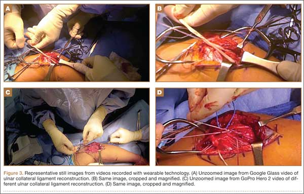
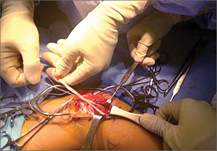
After successful recording of surgery, an effort should be made to produce a high-quality video for education or demonstration purposes. Unfortunately, there is no built-in optical zooming with Google Glass or GoPro, and recording segments in which surgeons focus on detailed anatomy (with high-quality zoom) may prove difficult. Online descriptions of do-it-yourself modifications to place zoom capability on GoPro devices may be useful in surgical video recording, particularly for small surgical fields (hand or foot surgery). In addition, footage may be zoomed in on during postprocessing (Figure 3), though some resolution will be lost in the editing.
There is no practical way to incorporate Google Glass or GoPro while using surgical loupes or a surgical microscope. As a result, videos recorded with wearable technology may not reach the minimum resolution needed for useful surgical technique videos, as these traditionally are produced on high-definition camcorders with optical zoom, allowing detailed viewing of anatomical structures without resolution loss through digital zoom or postprocessing editing.
There has been tremendous benefit in incorporating wearable technology into our practice. Videos made with Google Glass and GoPro have been successfully used for surgical preparation and training, allowing orthopedic surgical residents to rehearse surgery before participating in it. Alternatively, having used Google Glass or GoPro to record a case, residents have then been able to review each surgical step on video—thereby reinforcing their knowledge of the steps, techniques, pearls, and pitfalls before performing the surgery again. Footage from surgeries recorded with Google Glass and GoPro has also been shown at weekly technique-focused conferences, allowing surgeons to analyze particular steps and highlight applicable learning points. Last, attending surgeons in our practice have used wearable technology in “coaching” mode, either reviewing case footage to identify areas for improvement or sharing footage with senior surgeons in order to elicit feedback and suggestions for possible improvement.
As new iterations of wearable video technology come to market, with advancements in both hardware and software, surgeons may be able to enhance education and teaching through seamless recording of surgical procedures. Use of wearable technology may also begin to extend beyond the operating room—to outpatient settings, such as preoperative and postoperative physical examinations. The latest versions of Google Glass and GoPro Hero allow surgeons to record surgical procedures with relative ease, without the personnel, equipment, and coordination required for traditional surgical videography.
Video 1. Coracoid harvest for transfer during Latarjet procedure performed and filmed by Dr. Jobin using GoPro Hero 3.
The video associated with this article is no longer available on this site. Please view all of our videos on the MDedge YouTube channel
Video 2. Distal biceps repair performed by Dr. Makhni and Dr. Jobin, filmed by Dr. Makhni using Google Glass.
The video associated with this article is no longer available on this site. Please view all of our videos on the MDedge YouTube channel
1. Leahy M. Creating a good surgical technique video. AAOS Now. 2010;4(11). http://www.aaos.org/news/aaosnow/nov10/clinical4.asp. Accessed February 15, 2015.
2. Google Glass sales halted but firm says kit is not dead. BBC News website. http://www.bbc.com/news/technology-30831128. Published January 15, 2015. Accessed February 18, 2015.
3. Metz C. Sorry, but Google Glass isn’t anywhere close to dead. Wired website. http://www.wired.com/2015/02/sorry-google-glass-isnt-anywhere-close-dead/. Published February 8, 2015. Accessed February 18, 2015.
4. Peregrin T. Surgeons see future applications for Google Glass. Bull Am Coll Surg. 2014;99(7):9-16. http://bulletin.facs.org/2014/07/surgeons-see-future-applications-for-google-glass/#.U8SLKZaJAyZ.twitter. Accessed February 15, 2015.
Safe and efficient advanced surgical skill training is of tremendous importance. With the recent increase in Internet use for medical education, there has been a concomitant increase in video recording of surgical procedures and techniques. Surgical recordings have been used in a variety of ways—as live webcasts for remote participants, as “coaching” opportunities for surgeons evaluating their own performance in the operating room, and even as informational resources for patients about to undergo the same surgery.
Surgical multimedia is being delivered through several different outlets. Many academic conferences and meetings showcase videos of different procedures, and several subspecialty societies (eg, Arthroscopy Association of North America) house archives of technical videos for viewing by members. In addition, the VuMedi website offers videos and allows members to comment on them and interact with the videographers. Surgeons are even posting technique videos on YouTube and other public websites.
A large proportion of surgical multimedia is recorded with conventional high-definition video cameras.1 Besides being able to experience a case at any time and from outside the operating room, the audience can watch from numerous vantage points, angles, and zoom levels. Also, surgeons’ narration can be valuable in helping the audience follow along with the case.
Recording surgical multimedia historically required tight coordination and precise planning by surgeon and videographer. However, innovations in wearable technology now allow surgeons to literally wear video cameras and record procedures as they perform them, in real time—to act as both surgeon and videographer.
Two such products are Google Glass (Google, Mountain View, California) and GoPro Hero (GoPro, San Mateo, California), both of which allow surgeons to record exactly what they see during procedures (Figure 1). Using a wearable technology for surgical multimedia creation requires a deep familiarity with its capabilities and limitations. In this article, we summarize these products’ similarities and differences and provide a technical overview for using wearable technologies in surgical multimedia creation.
1. Choosing a device
When purchasing either wearable device, several factors must be considered, including budget, possible uses outside the operating room, and possible limitations of the technology (Table 1). At this time, Google Glass is significantly more expensive than GoPro Hero. The Google Glass base unit costs $1500, and the GoPro Hero 3 model costs approximately $200 (higher-priced Hero models are available). Both devices require accessories (eg, portable battery unit, dedicated hard drive).
Device capabilities must also be considered (Table 2). Google Glass consists of both hardware and software. Users can record what is seen and heard through the lens and then use apps to create text and e-mail portals to online gaming, social media, and even golf-course GPS. The app market for Google Glass is nascent but undoubtedly will increase in volume and scope as more users adopt the technology (Google Glass comes with both Bluetooth and Wi-Fi and can function tethered through a smartphone). GoPro is mainly a hardware unit that can record in various settings (it is popular with athletes who want to capture and broadcast their participation in action sports). Newer GoPro Hero versions offer Wi-Fi, which allows streaming of video content to a smartphone or tablet through an app. Having clearly defined goals for a device—as they pertain to use outside the operating room, such as outdoor activities and underwater recording—may help the surgeon decide which product is more suitable. Last, it is important to consider limitations. Google Glass resolution is 720p (1280×720) for video and 5 MP for still images, and GoPro resolution can reach 1080p (1920×1080) for video and 5 MP for stills.
Both devices require purchase of accessories. An external USB battery pack is useful for both devices, as is a password-encrypted hard drive for media storage. Lenswear does not come with the base version of Google Glass and is purchased separately from the company. GoPro users buy micro SD cards (~$50 per 64-GB high-speed transfer card) for storage on the device and may buy lithium-ion batteries as an alternative to the external USB battery pack.
Author Update
In January 2015, Google announced that it was temporarily suspending its “Explorer” program, which allowed individual users to buy and test the device for personal use. However, Google is continuing its development of Glass with health care technology, among other areas of growth and development.2,3
2. Recording a successful surgical video
Unlike a camcorder, which typically is set on a tripod for conventional video recording of surgery, Google Glass and GoPro are intricately linked to the operator. Surgeons must be constantly aware of where they are during surgery and try not to let anything obstruct the camera’s view.
Before starting a case, the surgeon using either device must ensure that its battery is fully charged, as a full charge typically supports 1 hour of continuous recording (the Google Glass battery is a lithium-ion 670-mAh internal unit). A full charge should be enough to capture a short case. Newer GoPro models, with a battery listed at 1050 mAh, provide 1 to 2 hours of recording. When more than 1 hour is needed, an external USB battery pack can be used. This pack allows the device to remain plugged in throughout the case (the pack is kept in the surgeon’s back pocket). We recommend having an external battery pack that is at least 10,000 mAh (~$30 online retail), which easily provides 3+ hours of recording. Unfortunately, this arrangement can be cumbersome. Alternatively, with GoPro, additional batteries may be purchased, but the user needs to dismount the device in order to swap them in (may be difficult during surgery). With both units, partitioning a video into shorter segments conserves battery power and minimizes the risk of file corruption, which may occur if the battery dies or the device overheats.
Google Glass users can bypass manual operation of the device by giving it voice commands (eg, start video, take still image). The exception is for recording video for more than 10 seconds (current default setting). Unfortunately, the surgeon must touch the device to start this recording, which means using extra gloves to preserve operating field sterility. Still images can be made through a combination of voice and head gestures and without manual intervention (Figure 2). Last, users must ensure that the device is not actively connected through Bluetooth to a mobile phone, as incoming calls, text messages, and e-mails may disrupt active recording and become a distraction. The connection can be deactivated by disabling Bluetooth on the host smartphone or by placing the phone into airplane mode and turning off Wi-Fi.
Google Glass users can see what is being recorded through the viewfinder prism, whereas GoPro requires precise framing of the video before recording. Framing is done by grossly aiming the device in the desired direction. However, there is no way to ensure exact aim during recording. If at any point during a case there is slight repositioning of the GoPro, there is a risk of recording the case out of the center of view. An important advantage to newer GoPro versions is the ability to control the device through a wireless remote that can be placed under the surgeon’s gown. The remote can be used to pause and resume recording, without changing gloves, as is done with Google Glass. Last, because the minimum viewing distance from the surgical field is usually 18 inches or more, typically there is no loss of focus or blurring of the image from short-distance recording on either device.
3. File management and playback
Before using wearable technology in the operating room, surgeons must become aware of its limitations with respect to file storage and playback. Google Glass has a usable memory of about 12 GB (1 hour of video may require 1.5-2.0 GB). Conversely, GoPro’s capacity is defined by the micro SD card used. Therefore, the Google Glass hard drive must be regularly maintained well before being brought into the operating room, whereas recording can be extended (with respect to memory) for the GoPro if the media card is large enough.
Both devices allow for wired file transfer, which may be done with Windows Explorer (PC) or iPhoto (Macintosh). However, Google Glass also allows for wireless transfer, through portable storage supported by Google. Although this type of file transfer may be convenient for short, everyday clips made outside the operating room, it is prohibitive for surgical media, mainly because of patient privacy concerns. With wireless transfer to a nonsecure cloud platform, there is a risk of breach of patient confidentiality. We therefore recommend against using wireless upload when producing surgical multimedia, as patient identifiers are likely to be included in the recorded audio or video contents. Conversely, with GoPro, the micro SD card can be used as a portable hard drive to transfer files to a laptop or media reader, obviating the need for wired or wireless transmission. Last, when using traditional wire transfer or memory card to upload to a hard drive, users must ensure that the drive complies with patient privacy laws and regulations.
4. Privacy and patient consent
As mentioned, great care must be taken to ensure that patient privacy laws are followed. This is especially relevant with content uploaded to online cloud storage, as with Google Glass. The upload may occur automatically if the unit is connected to a Wi-Fi hotspot. In addition, when using surgical media for a real-time webcast for education or demonstration purposes, surgeons must ensure that no protected health information is broadcast and that the patient and the surgical team are aware of the webcast and its purposes.
Before using wearable technology during patient care, patient consent must be obtained. Surgeons should ask the patient to consent to video recording of surgery or an encounter (eg, clinic visit) for education purposes. Our institution’s consent form includes a section for this particular type of consent. If an institution’s form lacks such a section, surgeons should consult their risk management department to ensure there is a proper avenue for obtaining patient consent to record the procedure or encounter. A separate, dedicated media consent form may be required. Last, whoever operates a wearable device should be careful to use the device only during encounters that have received explicit recording consent—as opposed to wearing the device in the hallways or elsewhere in the hospital, where protected health information might be inadvertently recorded.4
5. Putting it all to use
After successful recording of surgery, an effort should be made to produce a high-quality video for education or demonstration purposes. Unfortunately, there is no built-in optical zooming with Google Glass or GoPro, and recording segments in which surgeons focus on detailed anatomy (with high-quality zoom) may prove difficult. Online descriptions of do-it-yourself modifications to place zoom capability on GoPro devices may be useful in surgical video recording, particularly for small surgical fields (hand or foot surgery). In addition, footage may be zoomed in on during postprocessing (Figure 3), though some resolution will be lost in the editing.
There is no practical way to incorporate Google Glass or GoPro while using surgical loupes or a surgical microscope. As a result, videos recorded with wearable technology may not reach the minimum resolution needed for useful surgical technique videos, as these traditionally are produced on high-definition camcorders with optical zoom, allowing detailed viewing of anatomical structures without resolution loss through digital zoom or postprocessing editing.
There has been tremendous benefit in incorporating wearable technology into our practice. Videos made with Google Glass and GoPro have been successfully used for surgical preparation and training, allowing orthopedic surgical residents to rehearse surgery before participating in it. Alternatively, having used Google Glass or GoPro to record a case, residents have then been able to review each surgical step on video—thereby reinforcing their knowledge of the steps, techniques, pearls, and pitfalls before performing the surgery again. Footage from surgeries recorded with Google Glass and GoPro has also been shown at weekly technique-focused conferences, allowing surgeons to analyze particular steps and highlight applicable learning points. Last, attending surgeons in our practice have used wearable technology in “coaching” mode, either reviewing case footage to identify areas for improvement or sharing footage with senior surgeons in order to elicit feedback and suggestions for possible improvement.
As new iterations of wearable video technology come to market, with advancements in both hardware and software, surgeons may be able to enhance education and teaching through seamless recording of surgical procedures. Use of wearable technology may also begin to extend beyond the operating room—to outpatient settings, such as preoperative and postoperative physical examinations. The latest versions of Google Glass and GoPro Hero allow surgeons to record surgical procedures with relative ease, without the personnel, equipment, and coordination required for traditional surgical videography.
Video 1. Coracoid harvest for transfer during Latarjet procedure performed and filmed by Dr. Jobin using GoPro Hero 3.
The video associated with this article is no longer available on this site. Please view all of our videos on the MDedge YouTube channel
Video 2. Distal biceps repair performed by Dr. Makhni and Dr. Jobin, filmed by Dr. Makhni using Google Glass.
The video associated with this article is no longer available on this site. Please view all of our videos on the MDedge YouTube channel
1. Leahy M. Creating a good surgical technique video. AAOS Now. 2010;4(11). http://www.aaos.org/news/aaosnow/nov10/clinical4.asp. Accessed February 15, 2015.
2. Google Glass sales halted but firm says kit is not dead. BBC News website. http://www.bbc.com/news/technology-30831128. Published January 15, 2015. Accessed February 18, 2015.
3. Metz C. Sorry, but Google Glass isn’t anywhere close to dead. Wired website. http://www.wired.com/2015/02/sorry-google-glass-isnt-anywhere-close-dead/. Published February 8, 2015. Accessed February 18, 2015.
4. Peregrin T. Surgeons see future applications for Google Glass. Bull Am Coll Surg. 2014;99(7):9-16. http://bulletin.facs.org/2014/07/surgeons-see-future-applications-for-google-glass/#.U8SLKZaJAyZ.twitter. Accessed February 15, 2015.
Extensor Pollicis Longus Ruptures in Distal Radius Fractures: Clinical and Cadaveric Studies With a New Therapeutic Intervention
Distal radius fractures are among the most common upper extremity injuries. A Swedish study noted that 75% of forearm fractures involve the distal radius.1 Extensor pollicis longus (EPL) ruptures are a well-documented complication (0.3% incidence2) of distal radius fractures.
The first description of EPL ruptures is attributed to Duplay in 1876 and was termed drummer boy’s palsy.3 Spontaneous EPL ruptures are often described in the setting of acute or chronic tenosynovitis.4,5 Beginning in the early 1930s, multiple case reports began to connect distal radius fractures with EPL ruptures.6 Although EPL ruptures are rare, their consequences are substantial and typically necessitate reconstructive procedures. Extensor indicis proprius (EIP)-to-EPL tendon transfer has become a common surgical treatment for this complication. Increasing our knowledge of several characteristics associated with this complication may help clinically in preventing EPL ruptures.
Multiple studies have indicated that EPL ruptures occur more often in nondisplaced fractures and often occur between 6 and 8 weeks after injury.2,5,7,8 Several factors are implicated in the etiology of EPL ruptures in distal radius fractures. The classic 1979 study by Engkvist and Lundborg9 showed that the EPL tendon has an area of poor vascularity around the Lister tubercle. Explorations of nondisplaced distal radius fractures have shown an intact extensor retinaculum that allows the tendon to continue to travel through an enclosed space.4,5,7 In the setting of distal radius fracture, hematoma may contribute to tendon ruptures secondary to increased pressure within an intact third dorsal compartment, which further compromises vascularity in this region of the EPL tendon.
Recognition and prevention of an impending EPL rupture may help avoid the significant consequences of this complication. Decompression and release of the third dorsal compartment have been described as constituting a prophylactic surgical option.10,11 Early thumb range of motion is also advocated to help prevent EPL rupture.9 However, results reported in the literature are inconclusive as to the effectiveness of these or indeed any preventive procedures. Dr. Lourie uses a novel technique that involves aspiration of the third dorsal compartment in patients with clinical symptoms associated with impending EPL rupture. Needle decompression, a less invasive option, can be quickly performed in an office, and it is hypothesized that removal of the hematoma may prevent EPL ruptures.
In the present study, we retrospectively reviewed Dr. Lourie’s records of patients with EPL ruptures in association with distal radius fractures to help delineate which radiographic and clinical characteristics identify patients at risk for these ruptures. A cadaveric model of a nondisplaced distal radius fracture was then created in order to simulate a change in third compartment pressures before and after needle decompression. We present preliminary outcomes on a case series of 4 patients who underwent aspiration of the third compartment and who were thought to be at risk for EPL rupture.
Materials and Methods
Institutional review board approval was obtained for this study. From Dr. Lourie’s records, 19 patients treated between 1998 and 2009 were identified as having confirmed or clinically impending EPL ruptures in association with nonoperative treatment of distal radius fractures. Prodromal symptoms that were used to diagnose impending EPL ruptures included pain with resisted active EPL extension, pain with passive flexion of the thumb interphalangeal joint, and localized swelling over the third dorsal compartment of the wrist.5,7,10,12 Eleven patients had complete radiographs, which were reviewed for radiographic characteristics. Posteroanterior (PA) and lateral radiographs of the injured wrist were reviewed. On the PA radiographs, fraction location was measured from the tip of the radial styloid using a line perpendicular to the radial shaft. Fractures were also evaluated for displacement and intra-articular involvement.
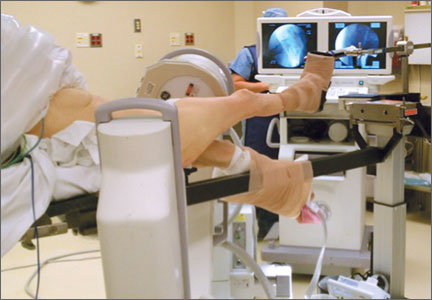
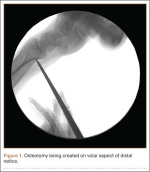
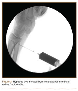
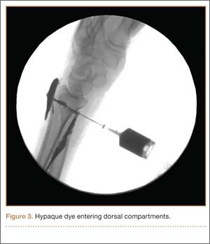
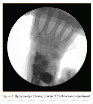
A cadaveric model was developed to evaluate compartment pressures in the EPL sheath in a simulated distal radius fracture. Six fresh-frozen cadaveric forearms were used after being thawed at room temperature. The cadavers were radiographically evaluated to determine that there was no evidence of prior fracture. A Stryker compartment pressure monitoring system (Stryker, Kalamazoo, Michigan) was used to take initial pressure readings in the third dorsal compartment slightly ulnar to the Lister tubercle (preinjection readings). A limited volar approach was then created. Under fluoroscopy, a half-inch osteotome was used to make an extra-articular fracture line in the distal radius, in the region of the Lister tubercle. The osteotomy was a mean of 1.2 cm from the distal aspect of the radius. The osteotomy site was then injected from the volar aspect with 5 mL of radiopaque (Hypaque) dye (Figure 1). Fluid extravasation into the third dorsal compartment was visualized under fluoroscopy (Figures 2–4). The monitor was then reinserted into the EPL sheath, and once again pressures were measured (postinjection readings). An 18-gauge needle was then used to aspirate the compartment just ulnar to the Lister tubercle. Compartment pressures were measured a final time (postaspiration readings). For all readings, 3 pressure measurements were recorded and then averaged. Pressure measurements were compared using t test.
In the office, the third dorsal compartment was aspirated after skin preparation with povidone-iodine. The Lister tubercle is typically palpable along the dorsal distal radius and is aligned with the cleft between the index and long fingers. Aspiration with an 18-gauge needle is performed just ulnar to the Lister tubercle in the EPL sheath, and hematoma is evacuated. The patient is then placed back into a long-arm cast or splint per the clinical situation.
Results
Patient age ranged from 17 to 81 years. Eight (1 male, 7 female) patients sustained an EPL rupture a mean of 46 days after initial trauma (range, 21-118 days). Two patients were treated with a prophylactic EPL transposition secondary to clinically apparent impending rupture, and 4 were treated with prophylactic needle decompression of the third compartment. Ruptures were treated with EIP-to-EPL transfers.
As in other studies, each patient’s radiographs showed a nondisplaced fracture and a transverse fracture line. Six patients also had a longitudinal, intra-articular fracture line that exited in a common spot between the scaphoid and the lunate facet.
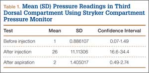
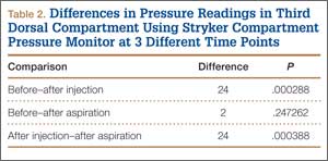
Results in our cadaveric model were consistent with those in in vitro decompression of the third dorsal compartment (Table 1). In the cadaver model, mean (SD) initial third dorsal compartment pressure was 0.77 (0.88) mm Hg. Mean (SD) pressure after osteotomy and Hypaque injection was 25.5 (11.11) mm Hg. After simulated therapeutic aspiration, mean (SD) pressure decreased to 1.61 (1.40) mm Hg. Mean change in pressure from after injection to after aspiration was 23.89 mm Hg (P = .000388) (Table 2).
Information from other studies and from Dr. Lourie’s experience was used to identify patients at significant risk for EPL ruptures in association with distal radius fractures. Four patients in Dr. Lourie’s practice between 2004 and 2009 had characteristic findings, including a nondisplaced distal radius fracture, localized swelling over the third dorsal compartment, and pain with resisted active EPL extension. Prophylactic aspiration and hematoma evacuation were performed in this series, yielding a mean hematoma amount of 2 mL (Table 3).
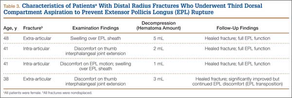
For all 4 patients, aspirations were performed within 2 weeks of injury. Subjectively, these patients described almost immediate pain relief and less discomfort with EPL motion after aspiration. Three of the 4 reported sustained pain relief on close follow-up 7 and 14 days after aspiration. The fourth patient continued to have pain over the third dorsal compartment, though she described it as significantly improved. Her initial fracture contained about 50% dorsal comminution, and she began to have a significant callus response. After 2 months of continued symptoms, and out of concern about consequences of an impending rupture, open decompression and transposition of the EPL were performed. In follow-up over 29 months, this patient continued to do well and had full EPL function. The 3 patients treated with aspiration alone have not had an EPL rupture (range of follow-up, 29-89 months).
Discussion
Distal radius fractures are very common injuries, and treating physicians must attempt to prevent possible complications. EPL tendon ruptures continue to be rare events (incidence, <1%) in association with distal radius fractures. Although statistics vary, studies have found a higher incidence in nondisplaced (vs displaced) distal radius fractures.5,7,10 Ruptures in nondisplaced fractures occur within 2 weeks to 3 years after injury but typically an average of 6 weeks after injury.2,4,7-9 Prodromal symptoms often include tenderness and swelling around the dorsal distal radius region around the Lister tubercle.7,11,12 Patients may complain of pain with active thumb extension or passive thumb range of motion.11 Rupture is indicated by an inability to actively extend the thumb.
Studies have shown that the tendon rupture site is around the Lister tubercle.7 No single cause for EPL ruptures has been confirmed, and the etiology is likely a mix of factors in relation to the clinical situation. Two theories have been espoused for the relation between EPL ruptures and distal radius fractures. The mechanical theory involves a prominent spicule of bone abrading the tendon and subsequently causing rupture.5,9 This seems less likely for nondisplaced fractures. The vascular theory centers on a watershed region of the EPL tendon around the Lister tubercle. Studies have found microangiographic evidence of a 5-mm portion of tendon around the Lister tubercle that has no mesotenon and poor vascularity.7,9 The tendon in this section may be reliant on synovial diffusion for nutrition,7 but hematoma may displace synovial fluid, interfering with tendon nutrition.
Researchers have studied the third dorsal compartment in patients with impending or established ruptures. In a series by Hirasawa and colleagues,7 11 patients with a nondisplaced fracture and a tendon rupture had an intact retinaculum and smooth bony surfaces on the dorsal radius. Periosteal hypertrophy and narrowing of the third compartment were noted. In another series, Helal and colleagues5 reported on 16 patients (nondisplaced and displaced fractures) who had possible EPL ruptures over a 4-year period. In all cases, the extensor retinaculum was intact. Likewise, the 7 patients with EPL ruptures in a series by Bonatz and colleagues4 had an intact extensor retinaculum. On exploration, Bunata10 noted fluid collections, including hematomas, within the sheath, as well as a lack of bony prominences. Simpson12 explored 2 cases of blunt trauma, no fracture, and subsequent EPL rupture. Clinically these 2 patients had swelling in the region of the Lister tubercle, and surgically they were found to have a distended, blood-filled sheath. These ruptures may correlate with nondisplaced distal radius fractures and provide further evidence supporting the vascular theory of ruptures. The combination of intact compartment and volume overload presents a situation akin to compartment syndrome. Acute compartment decompression with needle evacuation would theoretically relieve the vascular insult.
In the study by Helal and colleagues,5 Hypaque injections were given to patients with nondisplaced distal radius fractures. The dye remained in the third dorsal compartment, which implies an intact closed space. That study used a cadaveric model as well, with distal radius osteotomies performed to simulate a nondisplaced distal radius fracture. The authors noted an intact extensor retinaculum in their model. Our cadaver model is similar, except we measured pressures in the third compartment; our model indicated increased compartment pressures within the EPL sheath. Subsequent aspiration in our cadaveric study led to lower pressures in the third dorsal compartment. This cadaveric model implies that needle decompression of the third dorsal compartment may be beneficial in the setting of nondisplaced distal radius fractures and symptoms indicating a compromised EPL.
Splinting is an important factor that may help prevent EPL tendon ruptures after distal radius fractures. Synovial diffusion may be the primary mechanism for delivering nutrition to the EPL tendon.7 A splint that allows thumb metacarpophalangeal and interphalangeal flexion may provide the EPL motion needed for effective synovial nutritional pathways.9 Prodromal symptoms of tendon rupture should then be carefully monitored.
Conclusion
Results of our retrospective review are consistent with previous results elucidating the risk factors for EPL ruptures in association with distal radius fractures. In our patients who sustained EPL ruptures, findings included nondisplaced fractures, about 50% with an intra-articular component. Clinical findings included localized swelling over the third dorsal compartment, pain with resisted active EPL extension, and pain with passive flexion of the thumb interphalangeal joint. The cadaveric portion of this study indicated a significant change in pressure in the third dorsal compartment after aspiration. Preliminary outcomes in this 4-patient series are no EPL ruptures after prophylactic aspiration. Hematoma evacuation after nondisplaced distal radius fractures may become a useful addition to the surgeon’s armamentarium. Studies are needed to determine if needle aspiration of the third dorsal compartment can become an office-based procedure with value in preventing EPL ruptures in the appropriate clinical situation.
1. Alffram PA, Bauer GC. Epidemiology of fractures of the forearm. A biomechanical investigation of bone strength. J Bone Joint Surg Am. 1962;44:105-114.
2. Hove LM. Delayed rupture of the thumb extensor tendon. A 5-year study of 18 consecutive cases. Acta Orthop Scand. 1994;65(2):199-203.
3. Duplay. Rupture sous-cutanee du tendon du long extenseur du pouce, au niveau de la tabatiere anatomique. Bull Et Mem de la Soc de Chir de Paris. 1876.
4. Bonatz E, Kramer TD, Masear VR. Rupture of the extensor pollicis longus tendon. Am J Orthop. 1996;25(2):118-122.
5. Helal B, Chen SC, Iwegbu G. Rupture of the extensor pollicis longus tendon in undisplaced Colles’ type of fracture. Hand. 1982;14(1):41-47.
6. McMaster PE. Late ruptures of extensor and flexor pollicis longus tendons following Colles’ fracture. J Bone Joint Surg Am. 1932;14:93-101.
7. Hirasawa Y, Katsumi Y, Akiyoshi T, Tamai K, Tokioka T. Clinical and microangiographic studies on rupture of the E.P.L. tendon after distal radius fractures. J Hand Surg Br. 1990;15(1):51-57.
8. Björkman A, Jörgsholm P. Rupture of the extensor pollicis longus tendon: a study of aetiological factors. Scand J Plast Reconstruct Surg Hand Surg. 2004;38(1):32-35.
9. Engkvist O, Lundborg G. Rupture of the extensor pollicis longus tendon after fracture of the lower end of the radius—a clinical and microangiographic study. Hand. 1979;11(1):76-86.
10. Bunata RE. Impending rupture of the extensor pollicis longus tendon after a minimally displaced Colles fracture. A case report. J Bone Joint Surg Am. 1983;65(3):401-402.
11. Skoff HD. Postfracture extensor pollicis longus tenosynovitis and tendon rupture: a scientific study and personal series. Am J Orthop. 2003;32(5):245-247.
12. Simpson RG. Delayed rupture of extensor pollicis longus tendon following closed injury. Hand. 1977;9(2):160-161.
Distal radius fractures are among the most common upper extremity injuries. A Swedish study noted that 75% of forearm fractures involve the distal radius.1 Extensor pollicis longus (EPL) ruptures are a well-documented complication (0.3% incidence2) of distal radius fractures.
The first description of EPL ruptures is attributed to Duplay in 1876 and was termed drummer boy’s palsy.3 Spontaneous EPL ruptures are often described in the setting of acute or chronic tenosynovitis.4,5 Beginning in the early 1930s, multiple case reports began to connect distal radius fractures with EPL ruptures.6 Although EPL ruptures are rare, their consequences are substantial and typically necessitate reconstructive procedures. Extensor indicis proprius (EIP)-to-EPL tendon transfer has become a common surgical treatment for this complication. Increasing our knowledge of several characteristics associated with this complication may help clinically in preventing EPL ruptures.
Multiple studies have indicated that EPL ruptures occur more often in nondisplaced fractures and often occur between 6 and 8 weeks after injury.2,5,7,8 Several factors are implicated in the etiology of EPL ruptures in distal radius fractures. The classic 1979 study by Engkvist and Lundborg9 showed that the EPL tendon has an area of poor vascularity around the Lister tubercle. Explorations of nondisplaced distal radius fractures have shown an intact extensor retinaculum that allows the tendon to continue to travel through an enclosed space.4,5,7 In the setting of distal radius fracture, hematoma may contribute to tendon ruptures secondary to increased pressure within an intact third dorsal compartment, which further compromises vascularity in this region of the EPL tendon.
Recognition and prevention of an impending EPL rupture may help avoid the significant consequences of this complication. Decompression and release of the third dorsal compartment have been described as constituting a prophylactic surgical option.10,11 Early thumb range of motion is also advocated to help prevent EPL rupture.9 However, results reported in the literature are inconclusive as to the effectiveness of these or indeed any preventive procedures. Dr. Lourie uses a novel technique that involves aspiration of the third dorsal compartment in patients with clinical symptoms associated with impending EPL rupture. Needle decompression, a less invasive option, can be quickly performed in an office, and it is hypothesized that removal of the hematoma may prevent EPL ruptures.
In the present study, we retrospectively reviewed Dr. Lourie’s records of patients with EPL ruptures in association with distal radius fractures to help delineate which radiographic and clinical characteristics identify patients at risk for these ruptures. A cadaveric model of a nondisplaced distal radius fracture was then created in order to simulate a change in third compartment pressures before and after needle decompression. We present preliminary outcomes on a case series of 4 patients who underwent aspiration of the third compartment and who were thought to be at risk for EPL rupture.
Materials and Methods
Institutional review board approval was obtained for this study. From Dr. Lourie’s records, 19 patients treated between 1998 and 2009 were identified as having confirmed or clinically impending EPL ruptures in association with nonoperative treatment of distal radius fractures. Prodromal symptoms that were used to diagnose impending EPL ruptures included pain with resisted active EPL extension, pain with passive flexion of the thumb interphalangeal joint, and localized swelling over the third dorsal compartment of the wrist.5,7,10,12 Eleven patients had complete radiographs, which were reviewed for radiographic characteristics. Posteroanterior (PA) and lateral radiographs of the injured wrist were reviewed. On the PA radiographs, fraction location was measured from the tip of the radial styloid using a line perpendicular to the radial shaft. Fractures were also evaluated for displacement and intra-articular involvement.
A cadaveric model was developed to evaluate compartment pressures in the EPL sheath in a simulated distal radius fracture. Six fresh-frozen cadaveric forearms were used after being thawed at room temperature. The cadavers were radiographically evaluated to determine that there was no evidence of prior fracture. A Stryker compartment pressure monitoring system (Stryker, Kalamazoo, Michigan) was used to take initial pressure readings in the third dorsal compartment slightly ulnar to the Lister tubercle (preinjection readings). A limited volar approach was then created. Under fluoroscopy, a half-inch osteotome was used to make an extra-articular fracture line in the distal radius, in the region of the Lister tubercle. The osteotomy was a mean of 1.2 cm from the distal aspect of the radius. The osteotomy site was then injected from the volar aspect with 5 mL of radiopaque (Hypaque) dye (Figure 1). Fluid extravasation into the third dorsal compartment was visualized under fluoroscopy (Figures 2–4). The monitor was then reinserted into the EPL sheath, and once again pressures were measured (postinjection readings). An 18-gauge needle was then used to aspirate the compartment just ulnar to the Lister tubercle. Compartment pressures were measured a final time (postaspiration readings). For all readings, 3 pressure measurements were recorded and then averaged. Pressure measurements were compared using t test.
In the office, the third dorsal compartment was aspirated after skin preparation with povidone-iodine. The Lister tubercle is typically palpable along the dorsal distal radius and is aligned with the cleft between the index and long fingers. Aspiration with an 18-gauge needle is performed just ulnar to the Lister tubercle in the EPL sheath, and hematoma is evacuated. The patient is then placed back into a long-arm cast or splint per the clinical situation.
Results
Patient age ranged from 17 to 81 years. Eight (1 male, 7 female) patients sustained an EPL rupture a mean of 46 days after initial trauma (range, 21-118 days). Two patients were treated with a prophylactic EPL transposition secondary to clinically apparent impending rupture, and 4 were treated with prophylactic needle decompression of the third compartment. Ruptures were treated with EIP-to-EPL transfers.
As in other studies, each patient’s radiographs showed a nondisplaced fracture and a transverse fracture line. Six patients also had a longitudinal, intra-articular fracture line that exited in a common spot between the scaphoid and the lunate facet.
Results in our cadaveric model were consistent with those in in vitro decompression of the third dorsal compartment (Table 1). In the cadaver model, mean (SD) initial third dorsal compartment pressure was 0.77 (0.88) mm Hg. Mean (SD) pressure after osteotomy and Hypaque injection was 25.5 (11.11) mm Hg. After simulated therapeutic aspiration, mean (SD) pressure decreased to 1.61 (1.40) mm Hg. Mean change in pressure from after injection to after aspiration was 23.89 mm Hg (P = .000388) (Table 2).
Information from other studies and from Dr. Lourie’s experience was used to identify patients at significant risk for EPL ruptures in association with distal radius fractures. Four patients in Dr. Lourie’s practice between 2004 and 2009 had characteristic findings, including a nondisplaced distal radius fracture, localized swelling over the third dorsal compartment, and pain with resisted active EPL extension. Prophylactic aspiration and hematoma evacuation were performed in this series, yielding a mean hematoma amount of 2 mL (Table 3).
For all 4 patients, aspirations were performed within 2 weeks of injury. Subjectively, these patients described almost immediate pain relief and less discomfort with EPL motion after aspiration. Three of the 4 reported sustained pain relief on close follow-up 7 and 14 days after aspiration. The fourth patient continued to have pain over the third dorsal compartment, though she described it as significantly improved. Her initial fracture contained about 50% dorsal comminution, and she began to have a significant callus response. After 2 months of continued symptoms, and out of concern about consequences of an impending rupture, open decompression and transposition of the EPL were performed. In follow-up over 29 months, this patient continued to do well and had full EPL function. The 3 patients treated with aspiration alone have not had an EPL rupture (range of follow-up, 29-89 months).
Discussion
Distal radius fractures are very common injuries, and treating physicians must attempt to prevent possible complications. EPL tendon ruptures continue to be rare events (incidence, <1%) in association with distal radius fractures. Although statistics vary, studies have found a higher incidence in nondisplaced (vs displaced) distal radius fractures.5,7,10 Ruptures in nondisplaced fractures occur within 2 weeks to 3 years after injury but typically an average of 6 weeks after injury.2,4,7-9 Prodromal symptoms often include tenderness and swelling around the dorsal distal radius region around the Lister tubercle.7,11,12 Patients may complain of pain with active thumb extension or passive thumb range of motion.11 Rupture is indicated by an inability to actively extend the thumb.
Studies have shown that the tendon rupture site is around the Lister tubercle.7 No single cause for EPL ruptures has been confirmed, and the etiology is likely a mix of factors in relation to the clinical situation. Two theories have been espoused for the relation between EPL ruptures and distal radius fractures. The mechanical theory involves a prominent spicule of bone abrading the tendon and subsequently causing rupture.5,9 This seems less likely for nondisplaced fractures. The vascular theory centers on a watershed region of the EPL tendon around the Lister tubercle. Studies have found microangiographic evidence of a 5-mm portion of tendon around the Lister tubercle that has no mesotenon and poor vascularity.7,9 The tendon in this section may be reliant on synovial diffusion for nutrition,7 but hematoma may displace synovial fluid, interfering with tendon nutrition.
Researchers have studied the third dorsal compartment in patients with impending or established ruptures. In a series by Hirasawa and colleagues,7 11 patients with a nondisplaced fracture and a tendon rupture had an intact retinaculum and smooth bony surfaces on the dorsal radius. Periosteal hypertrophy and narrowing of the third compartment were noted. In another series, Helal and colleagues5 reported on 16 patients (nondisplaced and displaced fractures) who had possible EPL ruptures over a 4-year period. In all cases, the extensor retinaculum was intact. Likewise, the 7 patients with EPL ruptures in a series by Bonatz and colleagues4 had an intact extensor retinaculum. On exploration, Bunata10 noted fluid collections, including hematomas, within the sheath, as well as a lack of bony prominences. Simpson12 explored 2 cases of blunt trauma, no fracture, and subsequent EPL rupture. Clinically these 2 patients had swelling in the region of the Lister tubercle, and surgically they were found to have a distended, blood-filled sheath. These ruptures may correlate with nondisplaced distal radius fractures and provide further evidence supporting the vascular theory of ruptures. The combination of intact compartment and volume overload presents a situation akin to compartment syndrome. Acute compartment decompression with needle evacuation would theoretically relieve the vascular insult.
In the study by Helal and colleagues,5 Hypaque injections were given to patients with nondisplaced distal radius fractures. The dye remained in the third dorsal compartment, which implies an intact closed space. That study used a cadaveric model as well, with distal radius osteotomies performed to simulate a nondisplaced distal radius fracture. The authors noted an intact extensor retinaculum in their model. Our cadaver model is similar, except we measured pressures in the third compartment; our model indicated increased compartment pressures within the EPL sheath. Subsequent aspiration in our cadaveric study led to lower pressures in the third dorsal compartment. This cadaveric model implies that needle decompression of the third dorsal compartment may be beneficial in the setting of nondisplaced distal radius fractures and symptoms indicating a compromised EPL.
Splinting is an important factor that may help prevent EPL tendon ruptures after distal radius fractures. Synovial diffusion may be the primary mechanism for delivering nutrition to the EPL tendon.7 A splint that allows thumb metacarpophalangeal and interphalangeal flexion may provide the EPL motion needed for effective synovial nutritional pathways.9 Prodromal symptoms of tendon rupture should then be carefully monitored.
Conclusion
Results of our retrospective review are consistent with previous results elucidating the risk factors for EPL ruptures in association with distal radius fractures. In our patients who sustained EPL ruptures, findings included nondisplaced fractures, about 50% with an intra-articular component. Clinical findings included localized swelling over the third dorsal compartment, pain with resisted active EPL extension, and pain with passive flexion of the thumb interphalangeal joint. The cadaveric portion of this study indicated a significant change in pressure in the third dorsal compartment after aspiration. Preliminary outcomes in this 4-patient series are no EPL ruptures after prophylactic aspiration. Hematoma evacuation after nondisplaced distal radius fractures may become a useful addition to the surgeon’s armamentarium. Studies are needed to determine if needle aspiration of the third dorsal compartment can become an office-based procedure with value in preventing EPL ruptures in the appropriate clinical situation.
1. Alffram PA, Bauer GC. Epidemiology of fractures of the forearm. A biomechanical investigation of bone strength. J Bone Joint Surg Am. 1962;44:105-114.
2. Hove LM. Delayed rupture of the thumb extensor tendon. A 5-year study of 18 consecutive cases. Acta Orthop Scand. 1994;65(2):199-203.
3. Duplay. Rupture sous-cutanee du tendon du long extenseur du pouce, au niveau de la tabatiere anatomique. Bull Et Mem de la Soc de Chir de Paris. 1876.
4. Bonatz E, Kramer TD, Masear VR. Rupture of the extensor pollicis longus tendon. Am J Orthop. 1996;25(2):118-122.
5. Helal B, Chen SC, Iwegbu G. Rupture of the extensor pollicis longus tendon in undisplaced Colles’ type of fracture. Hand. 1982;14(1):41-47.
6. McMaster PE. Late ruptures of extensor and flexor pollicis longus tendons following Colles’ fracture. J Bone Joint Surg Am. 1932;14:93-101.
7. Hirasawa Y, Katsumi Y, Akiyoshi T, Tamai K, Tokioka T. Clinical and microangiographic studies on rupture of the E.P.L. tendon after distal radius fractures. J Hand Surg Br. 1990;15(1):51-57.
8. Björkman A, Jörgsholm P. Rupture of the extensor pollicis longus tendon: a study of aetiological factors. Scand J Plast Reconstruct Surg Hand Surg. 2004;38(1):32-35.
9. Engkvist O, Lundborg G. Rupture of the extensor pollicis longus tendon after fracture of the lower end of the radius—a clinical and microangiographic study. Hand. 1979;11(1):76-86.
10. Bunata RE. Impending rupture of the extensor pollicis longus tendon after a minimally displaced Colles fracture. A case report. J Bone Joint Surg Am. 1983;65(3):401-402.
11. Skoff HD. Postfracture extensor pollicis longus tenosynovitis and tendon rupture: a scientific study and personal series. Am J Orthop. 2003;32(5):245-247.
12. Simpson RG. Delayed rupture of extensor pollicis longus tendon following closed injury. Hand. 1977;9(2):160-161.
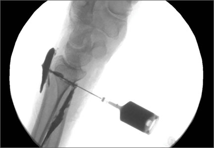
Arthroscopic Anterior Cruciate Ligament Reconstruction Using a Flexible Guide Pin With a Rigid Reamer
Anterior cruciate ligament (ACL) injuries are common, and arthroscopic ACL reconstruction is a routine procedure. Successful ACL reconstruction requires correct placement of the graft within the anatomical insertion of the native ACL.1-3 Errors in surgical technique—specifically, improper femoral tunnel placement—are the most common cause of graft failure in patients who present with recurrent instability after ACL reconstruction.4 There has been much emphasis on placing the tunnel more centrally in the ACL footprint as well as in a more horizontal position, which is thought to provide better rotational control and anterior-to-posterior translational stability.5-7
Two common techniques for creating the femoral tunnel, transtibial and anteromedial drilling, have their unique limitations. Transtibial drilling can place the tunnel high in the notch, resulting in nonanatomical, vertical graft placement.8,9 This technique can be modified to obtain a more anatomical tunnel, but the risk is the tunnel will be short and close to the joint line.10 To avoid these difficulties, surgeons began using an anteromedial portal.11,12 Although anteromedial drilling places the tunnel in a more anatomical position, it too has drawbacks, including the need to hyperflex the knee, a short tunnel, damage to articular cartilage, proximity to neurovascular structures, and difficulty in visualization during drilling.13-16
Femoral tunnel drilling techniques using flexible guide pins and reamers have been developed to address the limitations of rigid instruments. When we first started using flexible instruments through anteromedial portals, there were multiple incidents of reamer breakage during drilling. We therefore developed a technique that uses a flexible guide pin with a rigid reamer to place the femoral tunnel in an anatomical position. The patient described in this article provided written informed consent for print and electronic publication of this report.
Technique
We begin with our standard arthroscopic portals, including superolateral outflow, lateral parapatellar, and medial parapatellar portals. The medial parapatellar portal is placed under direct visualization with insertion of an 18-gauge spinal needle, ensuring the trajectory reaches the anatomical location of the native ACL on the lateral femoral condyle (LFC). The ACL stump is débrided with a shaver and a radiofrequency ablator, leaving a remnant of tissue to assist with tunnel placement. We do not routinely perform a notchplasty unless there is a concern about possible graft impingement, or the notch is abnormally small. The anatomical footprint is marked with a small awl (Figure 1), and the arthroscope is moved into the anteromedial portal to confirm anatomical placement of the awl mark (Figure 2).
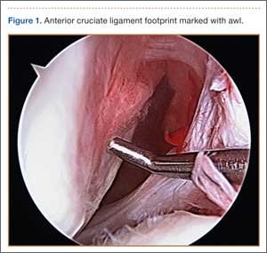
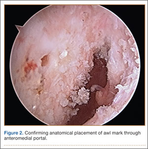
With the knee flexed to 100° to 110°, a flexible 2.7-mm nitonol guide pin (Smith & Nephew, Memphis, Tennessee) is placed freehand through the anteromedial portal into the anatomical footprint of the ACL, marked by the awl, and is passed through the femur before exiting the lateral skin. In most cases, we prefer freehand placement of the awl and pin; however, a femoral drill guide may be used to place the pin into the anatomical footprint of the ACL (Figure 3). The flexible pin allows for knee hyperflexion, clearance of the medial femoral condyle, central placement of the pin between the footprints of the anteromedial and posterolateral bundles for anatomical single-bundle reconstruction, and drilling of a long tunnel (average, 35-40 mm). The pin has a black laser marking that should be placed at the edge of the articular surface of the LFC to ensure appropriate depth of insertion (Figure 4).
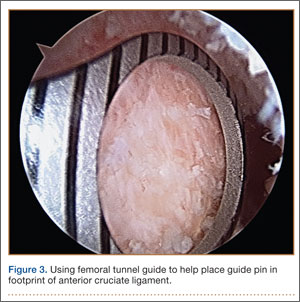
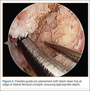
A small incision is then made around the guide wire on the lateral thigh, and an outside-in depth gauge is used to obtain an accurate length for the femoral tunnel. The gauge must abut the femoral cortex for accurate assessment of tunnel length. We use an Endobutton (Smith & Nephew) for fixation of the graft in the tunnel. The measured length of the tunnel is used to select an Endobutton of appropriate size and the proper reaming depth for suspension. We routinely use a 10- or 15-mm Endobutton, which provides an average 20 to 25 mm of graft inside the bony tunnel. The knee may then be relaxed to a normal resting flexion angle off the side of the bed, and the arthroscope is inserted into a medial portal or an accessory anteromedial portal to ensure anatomical placement of the pin. Using a flexible guide pin allows the knee to be relatively extended, providing good visualization of overall positioning in relation to the posterior wall of the LFC, whereas keeping the knee in a flexed position (as with a rigid guide pin) can often compromise this visualization.
Using a solid reamer corresponding to the size of the graft, we drill over the guide pin to the appropriate depth, again with the knee hyperflexed (Figure 5), making sure not to breach the lateral femoral cortex, which would compromise fixation with the Endobutton. After drilling with the rigid reamer is completed, placement of the tunnel in an anatomical position is again confirmed with the knee in the normal resting flexion angle (Figure 6). Once the tibial tunnel is drilled at the anatomical footprint, the graft is passed with the proper-length Endobutton and is fixed on the tibial side with a bioabsorbable interference screw 1 to 2 mm larger than the soft-tissue graft and tibial tunnel size. The knee is flexed to 30° while the tibial screw is placed. Graft tension and impingement are then checked (Figure 7). Postoperative anteroposterior and lateral radiographs of the knee may be obtained to confirm anatomical placement of the tunnels as well as proper positioning of the Endobutton (Figures 8A, 8B).
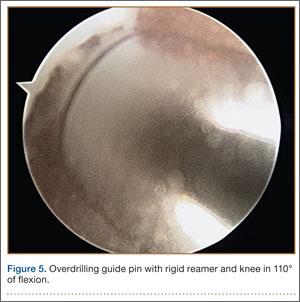
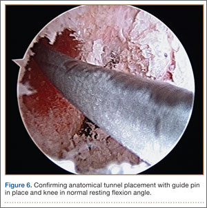
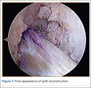
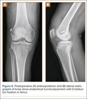
Discussion
Successful ACL reconstruction depends heavily on anatomical tunnel positioning. Failure to place the femoral tunnel in the anatomical footprint of the native ACL results in incomplete restoration of knee kinematics, rotational instability, and graft failure.1-7 Two common techniques for creating this tunnel, transtibial and anteromedial drilling, can reliably place it in an anatomical position. Each technique, however, has limitations. Transtibial drilling can place the tunnel too vertical and high in the notch, or produce a short tibial tunnel close to the joint line.8-10 Anteromedial drilling requires knee hyperflexion, risks damaging the articular cartilage and nearby neurovascular structures, and makes visualization difficult.13-16
One option for addressing some of the difficulties and limitations with anteromedial drilling is to use flexible guide pins and reamers, as first introduced by Cain and Clancy.1 In a cadaveric study, Silver and colleagues17 demonstrated that interosseous tunnels drilled with flexible guide pins were on average more than 6 mm longer than those drilled with rigid pins and consistently were 40 mm or longer. In addition, all tunnels drilled with flexible guide pins were on average 42.3 mm away from the peroneal nerve and 26.1 mm away from the femoral origin of the lateral collateral ligament—safe distances.
Steiner and Smart18 compared flexible and rigid instruments used to drill transtibial and anteromedial (without hyperflexion) anatomical femoral tunnels in ACL reconstruction in cadaveric knees. Although transtibial drilling with flexible pins produced anatomical tunnels, the tunnels were shorter, and the pins exited more posterior in comparison with anteromedial drilling with flexible pins. Transtibial tunnels drilled with rigid pins were nonanatomical and exited more superior and anterior on the femur, resulting in longer tunnels. Anteromedial tunnels drilled with rigid and flexible pins were placed anatomically, but flexible pins produced longer tunnels, did not require hyperflexion (120°), could easily be placed with the knee in 90° of flexion, and did not violate the posterior femoral cortex.
Five times in our early experience with flexible guide pins and reamers, the reamer broke when LFC reaming was initiated. In each case, the broken reamer was retrieved. However, these complications resulted in increased surgical time and cost. In addition, an unretrievable reamer could have caused further injury and suboptimal outcomes. We subsequently developed an anteromedial technique that uses a flexible guide pin with a rigid reamer to place the femoral tunnel in an anatomical position (Figure 9). The flexible pin provides consistent placement of anatomical tunnels averaging 35 to 40 mm in length. Use of the flexible pin does not require constant hyperflexion of the knee, and it allows for better visualization of the posterior wall of the LFC, ensures anatomical graft placement, and decreases the risk of damaging articular cartilage and causing neurovascular injury. Use of the rigid reamer negates the risks and additional costs associated with reamer breakage. It is unclear why 5 flexible reamers broke during our early use of flexible guide pins and reamers, but it is possible that, because of the patients’ anatomy, placement of the pin in the correct anatomical position in the ACL footprint put a significant amount of abnormal stress on the reamer during tunnel reaming, leading to breakage and failure.
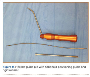
A short femoral tunnel is a common complication of using an anteromedial portal for tunnel drilling.13-16 With the technique we have been using, tunnel lengths average 35 to 40 mm. To address the occasional shorter tunnel, we use Endobutton Direct (Smith & Nephew), which allows for direct fixation of the graft on the button, maximizing the amount of graft in the femoral tunnel and minimizing graft–tunnel length mismatch. In the event there is a lateral wall breach during overdrilling with the reamer, the femoral graft may be secured with screw and post, with interference screw, or with the larger Xtendobuton (Smith & Nephew).
We have successfully used this technique with bone–patellar tendon–bone (BPTB) and hamstring autografts, as well as allografts. Complications, such as graft–tunnel length mismatch, have been uncommon, but, when using BPTB grafts, passing the bone block into the femoral tunnel can be difficult because of the sharp turn required.
Conclusion
Successful ACL reconstruction depends heavily on placement of the graft within the anatomical insertion of the native ACL. With the development of techniques that use flexible guide pins and reamers, it has become possible to place longer anatomical femoral tunnels without the need for hyperflexion. Use of a flexible guide pin with a rigid reamer allows placement of longer anatomical tunnels through an anteromedial portal, reduces time spent with the knee in hyperflexion, provides better viewing, poses less risk of damage to the articular cartilage and neurovascular structures, and at a lower cost with less risk of reamer breakage. In addition, this technique can be used with a variety of graft options, including BPTB grafts, hamstring autografts, and allografts.
1. Cain EL Jr, Clancy WG Jr. Anatomic endoscopic anterior cruciate ligament reconstruction with patella tendon autograft. Orthop Clin North Am. 2002;33(4):717-725.
2. Chhabra A, Starman JS, Ferretti M, Vidal AF, Zantop T, Fu FH. Anatomic, radiographic, biomechanical, and kinematic evaluation of the anterior cruciate ligament and its two functional bundles. J Bone Joint Surg Am. 2006;88(suppl 4):2-10.
3. Christel P, Sahasrabudhe A, Basdekis G. Anatomic double-bundle anterior cruciate ligament reconstruction with anatomic aimers. Arthroscopy. 2008;24(10):1146-1151.
4. Allen CR, Giffin JR, Harner CD. Revision anterior cruciate ligament reconstruction. Orthop Clin North Am. 2003;34(1):79-98.
5. Miller CD, Gerdeman AC, Hart JM, et al. A comparison of 2 drilling techniques on the femoral tunnel for anterior cruciate ligament reconstruction. Arthroscopy. 2011;27(3):372-379.
6. Seon JK, Park SJ, Lee KB, Seo HY, Kim MS, Song EK. In vivo stability and clinical comparison of anterior cruciate ligament reconstruction using low or high femoral tunnel positions. Am J Sports Med. 2011;39(1):127-133.
7. Steiner ME, Battaglia TC, Heming JF, Rand JD, Festa A, Baria M. Independent drilling outperforms conventional transtibial drilling in anterior cruciate ligament reconstruction. Am J Sports Med. 2009;37(10):1912-1919.
8. Kopf S, Forsythe B, Wong AK, et al. Nonanatomic tunnel position in traditional transtibial single-bundle anterior cruciate ligament reconstruction evaluated by three-dimensional computed tomography. J Bone Joint Surg Am. 2010;92(6):1427-1431.
9. Tompkins M, Milewski MD, Brockmeier SF, Gaskin CM, Hart JM, Miller MD. Anatomic femoral tunnel drilling in anterior cruciate ligament reconstruction: use of an accessory medial portal versus traditional transtibial drilling. Am J Sports Med. 2012;40(6):1313-1321.
10. Heming JF, Rand J, Steiner ME. Anatomical limitations of transtibial drilling in anterior cruciate ligament reconstruction. Am J Sports Med. 2007;35(10):1708-1715.
11. Harner CD, Honkamp NJ, Ranawat AS. Anteromedial portal technique for creating the anterior cruciate ligament femoral tunnel. Arthroscopy. 2008;24(1):113-115.
12. Lubowitz JH. Anteromedial portal technique for the anterior cruciate ligament femoral socket: pitfalls and solutions. Arthroscopy. 2009;25(1):95-101.
13. Basdekis G, Abisafi C, Christel P. Influence of knee flexion angle on femoral tunnel characteristics when drilled through the anteromedial portal during anterior cruciate ligament reconstruction. Arthroscopy. 2008;24(4):459-464.
14. Zantop T, Haase AK, Fu FH, Petersen W. Potential risk of cartilage damage in double bundle ACL reconstruction: impact of knee flexion angle and portal location on the femoral PL bundle tunnel. Arch Orthop Trauma Surg. 2008;128(5):509-513.
15. Farrow LD, Parker RD. The relationship of lateral anatomic structures to exiting guide pins during femoral tunnel preparation utilizing an accessory medial portal. Knee Surg Sports Traumatol Arthrosc. 2010;18(6):747-753.
16. Nakamura M, Deie M, Shibuya H, et al. Potential risks of femoral tunnel drilling through the far anteromedial portal: a cadaveric study. Arthroscopy. 2009;25(5):481-487.
17. Silver AG, Kaar SG, Grisell MK, Reagan JM, Farrow LD. Comparison between rigid and flexible systems for drilling the femoral tunnel through an anteromedial portal in anterior cruciate ligament reconstruction. Arthroscopy. 2010;26(6):790-795.
18. Steiner ME, Smart LR. Flexible instruments outperform rigid instruments to place anatomic anterior cruciate ligament femoral tunnels without hyperflexion. Arthroscopy. 2012;28(6):835-843.
Anterior cruciate ligament (ACL) injuries are common, and arthroscopic ACL reconstruction is a routine procedure. Successful ACL reconstruction requires correct placement of the graft within the anatomical insertion of the native ACL.1-3 Errors in surgical technique—specifically, improper femoral tunnel placement—are the most common cause of graft failure in patients who present with recurrent instability after ACL reconstruction.4 There has been much emphasis on placing the tunnel more centrally in the ACL footprint as well as in a more horizontal position, which is thought to provide better rotational control and anterior-to-posterior translational stability.5-7
Two common techniques for creating the femoral tunnel, transtibial and anteromedial drilling, have their unique limitations. Transtibial drilling can place the tunnel high in the notch, resulting in nonanatomical, vertical graft placement.8,9 This technique can be modified to obtain a more anatomical tunnel, but the risk is the tunnel will be short and close to the joint line.10 To avoid these difficulties, surgeons began using an anteromedial portal.11,12 Although anteromedial drilling places the tunnel in a more anatomical position, it too has drawbacks, including the need to hyperflex the knee, a short tunnel, damage to articular cartilage, proximity to neurovascular structures, and difficulty in visualization during drilling.13-16
Femoral tunnel drilling techniques using flexible guide pins and reamers have been developed to address the limitations of rigid instruments. When we first started using flexible instruments through anteromedial portals, there were multiple incidents of reamer breakage during drilling. We therefore developed a technique that uses a flexible guide pin with a rigid reamer to place the femoral tunnel in an anatomical position. The patient described in this article provided written informed consent for print and electronic publication of this report.
Technique
We begin with our standard arthroscopic portals, including superolateral outflow, lateral parapatellar, and medial parapatellar portals. The medial parapatellar portal is placed under direct visualization with insertion of an 18-gauge spinal needle, ensuring the trajectory reaches the anatomical location of the native ACL on the lateral femoral condyle (LFC). The ACL stump is débrided with a shaver and a radiofrequency ablator, leaving a remnant of tissue to assist with tunnel placement. We do not routinely perform a notchplasty unless there is a concern about possible graft impingement, or the notch is abnormally small. The anatomical footprint is marked with a small awl (Figure 1), and the arthroscope is moved into the anteromedial portal to confirm anatomical placement of the awl mark (Figure 2).
With the knee flexed to 100° to 110°, a flexible 2.7-mm nitonol guide pin (Smith & Nephew, Memphis, Tennessee) is placed freehand through the anteromedial portal into the anatomical footprint of the ACL, marked by the awl, and is passed through the femur before exiting the lateral skin. In most cases, we prefer freehand placement of the awl and pin; however, a femoral drill guide may be used to place the pin into the anatomical footprint of the ACL (Figure 3). The flexible pin allows for knee hyperflexion, clearance of the medial femoral condyle, central placement of the pin between the footprints of the anteromedial and posterolateral bundles for anatomical single-bundle reconstruction, and drilling of a long tunnel (average, 35-40 mm). The pin has a black laser marking that should be placed at the edge of the articular surface of the LFC to ensure appropriate depth of insertion (Figure 4).
A small incision is then made around the guide wire on the lateral thigh, and an outside-in depth gauge is used to obtain an accurate length for the femoral tunnel. The gauge must abut the femoral cortex for accurate assessment of tunnel length. We use an Endobutton (Smith & Nephew) for fixation of the graft in the tunnel. The measured length of the tunnel is used to select an Endobutton of appropriate size and the proper reaming depth for suspension. We routinely use a 10- or 15-mm Endobutton, which provides an average 20 to 25 mm of graft inside the bony tunnel. The knee may then be relaxed to a normal resting flexion angle off the side of the bed, and the arthroscope is inserted into a medial portal or an accessory anteromedial portal to ensure anatomical placement of the pin. Using a flexible guide pin allows the knee to be relatively extended, providing good visualization of overall positioning in relation to the posterior wall of the LFC, whereas keeping the knee in a flexed position (as with a rigid guide pin) can often compromise this visualization.
Using a solid reamer corresponding to the size of the graft, we drill over the guide pin to the appropriate depth, again with the knee hyperflexed (Figure 5), making sure not to breach the lateral femoral cortex, which would compromise fixation with the Endobutton. After drilling with the rigid reamer is completed, placement of the tunnel in an anatomical position is again confirmed with the knee in the normal resting flexion angle (Figure 6). Once the tibial tunnel is drilled at the anatomical footprint, the graft is passed with the proper-length Endobutton and is fixed on the tibial side with a bioabsorbable interference screw 1 to 2 mm larger than the soft-tissue graft and tibial tunnel size. The knee is flexed to 30° while the tibial screw is placed. Graft tension and impingement are then checked (Figure 7). Postoperative anteroposterior and lateral radiographs of the knee may be obtained to confirm anatomical placement of the tunnels as well as proper positioning of the Endobutton (Figures 8A, 8B).
Discussion
Successful ACL reconstruction depends heavily on anatomical tunnel positioning. Failure to place the femoral tunnel in the anatomical footprint of the native ACL results in incomplete restoration of knee kinematics, rotational instability, and graft failure.1-7 Two common techniques for creating this tunnel, transtibial and anteromedial drilling, can reliably place it in an anatomical position. Each technique, however, has limitations. Transtibial drilling can place the tunnel too vertical and high in the notch, or produce a short tibial tunnel close to the joint line.8-10 Anteromedial drilling requires knee hyperflexion, risks damaging the articular cartilage and nearby neurovascular structures, and makes visualization difficult.13-16
One option for addressing some of the difficulties and limitations with anteromedial drilling is to use flexible guide pins and reamers, as first introduced by Cain and Clancy.1 In a cadaveric study, Silver and colleagues17 demonstrated that interosseous tunnels drilled with flexible guide pins were on average more than 6 mm longer than those drilled with rigid pins and consistently were 40 mm or longer. In addition, all tunnels drilled with flexible guide pins were on average 42.3 mm away from the peroneal nerve and 26.1 mm away from the femoral origin of the lateral collateral ligament—safe distances.
Steiner and Smart18 compared flexible and rigid instruments used to drill transtibial and anteromedial (without hyperflexion) anatomical femoral tunnels in ACL reconstruction in cadaveric knees. Although transtibial drilling with flexible pins produced anatomical tunnels, the tunnels were shorter, and the pins exited more posterior in comparison with anteromedial drilling with flexible pins. Transtibial tunnels drilled with rigid pins were nonanatomical and exited more superior and anterior on the femur, resulting in longer tunnels. Anteromedial tunnels drilled with rigid and flexible pins were placed anatomically, but flexible pins produced longer tunnels, did not require hyperflexion (120°), could easily be placed with the knee in 90° of flexion, and did not violate the posterior femoral cortex.
Five times in our early experience with flexible guide pins and reamers, the reamer broke when LFC reaming was initiated. In each case, the broken reamer was retrieved. However, these complications resulted in increased surgical time and cost. In addition, an unretrievable reamer could have caused further injury and suboptimal outcomes. We subsequently developed an anteromedial technique that uses a flexible guide pin with a rigid reamer to place the femoral tunnel in an anatomical position (Figure 9). The flexible pin provides consistent placement of anatomical tunnels averaging 35 to 40 mm in length. Use of the flexible pin does not require constant hyperflexion of the knee, and it allows for better visualization of the posterior wall of the LFC, ensures anatomical graft placement, and decreases the risk of damaging articular cartilage and causing neurovascular injury. Use of the rigid reamer negates the risks and additional costs associated with reamer breakage. It is unclear why 5 flexible reamers broke during our early use of flexible guide pins and reamers, but it is possible that, because of the patients’ anatomy, placement of the pin in the correct anatomical position in the ACL footprint put a significant amount of abnormal stress on the reamer during tunnel reaming, leading to breakage and failure.
A short femoral tunnel is a common complication of using an anteromedial portal for tunnel drilling.13-16 With the technique we have been using, tunnel lengths average 35 to 40 mm. To address the occasional shorter tunnel, we use Endobutton Direct (Smith & Nephew), which allows for direct fixation of the graft on the button, maximizing the amount of graft in the femoral tunnel and minimizing graft–tunnel length mismatch. In the event there is a lateral wall breach during overdrilling with the reamer, the femoral graft may be secured with screw and post, with interference screw, or with the larger Xtendobuton (Smith & Nephew).
We have successfully used this technique with bone–patellar tendon–bone (BPTB) and hamstring autografts, as well as allografts. Complications, such as graft–tunnel length mismatch, have been uncommon, but, when using BPTB grafts, passing the bone block into the femoral tunnel can be difficult because of the sharp turn required.
Conclusion
Successful ACL reconstruction depends heavily on placement of the graft within the anatomical insertion of the native ACL. With the development of techniques that use flexible guide pins and reamers, it has become possible to place longer anatomical femoral tunnels without the need for hyperflexion. Use of a flexible guide pin with a rigid reamer allows placement of longer anatomical tunnels through an anteromedial portal, reduces time spent with the knee in hyperflexion, provides better viewing, poses less risk of damage to the articular cartilage and neurovascular structures, and at a lower cost with less risk of reamer breakage. In addition, this technique can be used with a variety of graft options, including BPTB grafts, hamstring autografts, and allografts.
1. Cain EL Jr, Clancy WG Jr. Anatomic endoscopic anterior cruciate ligament reconstruction with patella tendon autograft. Orthop Clin North Am. 2002;33(4):717-725.
2. Chhabra A, Starman JS, Ferretti M, Vidal AF, Zantop T, Fu FH. Anatomic, radiographic, biomechanical, and kinematic evaluation of the anterior cruciate ligament and its two functional bundles. J Bone Joint Surg Am. 2006;88(suppl 4):2-10.
3. Christel P, Sahasrabudhe A, Basdekis G. Anatomic double-bundle anterior cruciate ligament reconstruction with anatomic aimers. Arthroscopy. 2008;24(10):1146-1151.
4. Allen CR, Giffin JR, Harner CD. Revision anterior cruciate ligament reconstruction. Orthop Clin North Am. 2003;34(1):79-98.
5. Miller CD, Gerdeman AC, Hart JM, et al. A comparison of 2 drilling techniques on the femoral tunnel for anterior cruciate ligament reconstruction. Arthroscopy. 2011;27(3):372-379.
6. Seon JK, Park SJ, Lee KB, Seo HY, Kim MS, Song EK. In vivo stability and clinical comparison of anterior cruciate ligament reconstruction using low or high femoral tunnel positions. Am J Sports Med. 2011;39(1):127-133.
7. Steiner ME, Battaglia TC, Heming JF, Rand JD, Festa A, Baria M. Independent drilling outperforms conventional transtibial drilling in anterior cruciate ligament reconstruction. Am J Sports Med. 2009;37(10):1912-1919.
8. Kopf S, Forsythe B, Wong AK, et al. Nonanatomic tunnel position in traditional transtibial single-bundle anterior cruciate ligament reconstruction evaluated by three-dimensional computed tomography. J Bone Joint Surg Am. 2010;92(6):1427-1431.
9. Tompkins M, Milewski MD, Brockmeier SF, Gaskin CM, Hart JM, Miller MD. Anatomic femoral tunnel drilling in anterior cruciate ligament reconstruction: use of an accessory medial portal versus traditional transtibial drilling. Am J Sports Med. 2012;40(6):1313-1321.
10. Heming JF, Rand J, Steiner ME. Anatomical limitations of transtibial drilling in anterior cruciate ligament reconstruction. Am J Sports Med. 2007;35(10):1708-1715.
11. Harner CD, Honkamp NJ, Ranawat AS. Anteromedial portal technique for creating the anterior cruciate ligament femoral tunnel. Arthroscopy. 2008;24(1):113-115.
12. Lubowitz JH. Anteromedial portal technique for the anterior cruciate ligament femoral socket: pitfalls and solutions. Arthroscopy. 2009;25(1):95-101.
13. Basdekis G, Abisafi C, Christel P. Influence of knee flexion angle on femoral tunnel characteristics when drilled through the anteromedial portal during anterior cruciate ligament reconstruction. Arthroscopy. 2008;24(4):459-464.
14. Zantop T, Haase AK, Fu FH, Petersen W. Potential risk of cartilage damage in double bundle ACL reconstruction: impact of knee flexion angle and portal location on the femoral PL bundle tunnel. Arch Orthop Trauma Surg. 2008;128(5):509-513.
15. Farrow LD, Parker RD. The relationship of lateral anatomic structures to exiting guide pins during femoral tunnel preparation utilizing an accessory medial portal. Knee Surg Sports Traumatol Arthrosc. 2010;18(6):747-753.
16. Nakamura M, Deie M, Shibuya H, et al. Potential risks of femoral tunnel drilling through the far anteromedial portal: a cadaveric study. Arthroscopy. 2009;25(5):481-487.
17. Silver AG, Kaar SG, Grisell MK, Reagan JM, Farrow LD. Comparison between rigid and flexible systems for drilling the femoral tunnel through an anteromedial portal in anterior cruciate ligament reconstruction. Arthroscopy. 2010;26(6):790-795.
18. Steiner ME, Smart LR. Flexible instruments outperform rigid instruments to place anatomic anterior cruciate ligament femoral tunnels without hyperflexion. Arthroscopy. 2012;28(6):835-843.
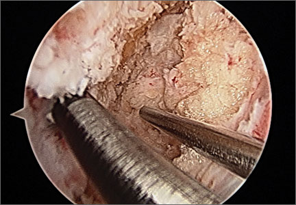
A Novel Treatment for Refractory Plantar Fasciitis
Chronic plantar fasciitis is a major health care problem worldwide and affects nearly 10% of the US population. Plantar fasciitis presents as heel pain in the mornings and usually gets better and then gets worse. Inflammation at the plantar fascia attachment causes acute and sometimes disabling pain. Chronic pain at the site can develop as time goes on because of long-standing inflammatory changes. Fibrotic tissues may develop at the site. On a continuum, symptoms may begin in an insidious phase and progress to chronic pain. Although most cases resolve with conservative care, the numerous treatments for refractory plantar fasciitis attest to the lack of consensus regarding these cases. The condition frustrates patient and physician alike.
Treatments for refractory plantar fasciitis include conservative measures, including rest, analgesics, walking orthosis, heel cup, night splint, walking boot, and then, in a standard and logical progression, cortisone or platelet-rich plasma injections. Improved magnetic resonance imaging and ultrasonographic imaging allow accurate localization of the pathologic process,1-3 and this localization in turn provides an opportunity to deliver a more reliable and focused intervention, as in needle-guided therapy.4 Surgical procedures for plantar fasciitis have included open or endoscopically assisted plantar fasciectomies with or without gastrocnemius recession; these procedures have had varying results. The emerging goals for this condition are a minimally invasive percutaneous intervention that is safe, effective, and well-tolerated and has minimal morbidity and a low complication rate.
We conducted a prospective study in which patients were allowed either to continue with noninvasive treatment or to undergo focal aspiration and partial fasciotomy with an ultrasonic probe. Study inclusion criteria were plantar fasciitis symptoms lasting 12 months or longer. Exclusion criteria were unwillingness to participate in the study. Prior treatments, even surgeries, were not exclusionary.
Twelve patients with refractory plantar fasciitis lasting a mean of 19 months (minimum, 12 months; range, 12-24 months) chose the procedure. They all had failed conservative care, including physical therapy, casting, shockwave therapy, and invasive procedures such as injections and endoscopic partial releases. Four of the 12 had undergone an open or endoscopic partial release at a different institution but had experienced no improvement in symptoms.
Based on the study protocol, patients continued noninvasive care (night splint, stretching exercises) for 2 to 6 weeks after the initial visit. When this conservative care failed, they were offered focal partial fasciectomy with a percutaneous ultrasonic probe. American Orthopaedic Foot and Ankle Society (AOFAS) scores were obtained before and after surgery. Follow-up consisted of clinic visits 2 weeks after surgery and monthly thereafter. I saw all 12 patients 3 months after surgery (range, 11-14 weeks), and all 12 underwent postoperative physical therapy.
Technique
The TX1 Tissue Removal System (Tenex Health, Lake Forest, California) (Figure 1) consists of an energy module, a pump/suction cassette that provides irrigation and suction through a probe, and the probe itself, the TX1, which is the size of an 18-gauge needle and delivers ultrasonic energy. The cassette is inserted into the energy module, and the ultrasonic energy probe is primed so it will deliver the irrigation fluid, normal saline. The safety features of the energy module are such that no energy is expended unless the system is properly irrigating and aspirating the diseased tissue. Ultrasonic treatment may be performed in a clinical or ambulatory surgical center. The patient is placed supine on an operating table, on a clinical examining table, or, if in a cast room, on a cart. A pillow is placed under the distal tibia so the knees can flex slightly, and the patient is positioned so the feet are free of the edge of the bed or gurney (Figure 2).
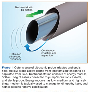
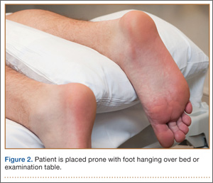
The pathology is first confirmed by ultrasonography (Figures 3–5). The first step is to identify the calcaneus with the sensor along the long axis of the foot. Then the plantar fascia is visualized and followed along its long axis to the site of attachment at the medial tubercle. As the pathologic process involves the medial site of attachment, a transverse image may also be obtained to better understand the medial/lateral extent of the disease process. The ultrasonographic image of plantar fasciitis has been well characterized.2,5 The pathology is visualized as an area of edema or of disruption of the linear appearance of the fascia as it attaches to the calcaneus. While the diagnosis is being confirmed, the optimal site for probe insertion should be considered based on the location of the pain and the localization of the pathology by the 2 orthogonal images.
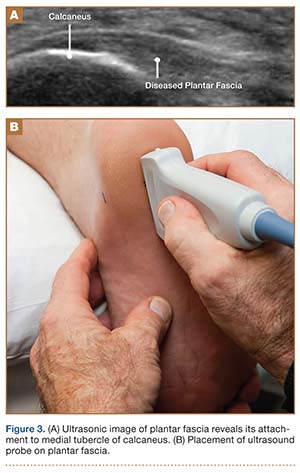
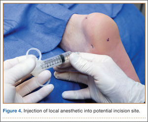
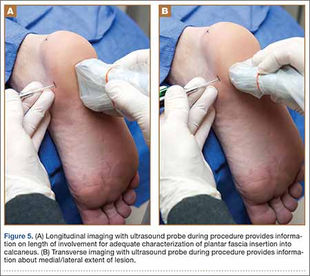
The area is prepared as if for an injection and is squared off with sterile towels. Then the sensor is placed in the sterile sleeve. The area of maximum tenderness is again confirmed. Determining the location of the probe insertion site is a crucial step. We use the ultrasonic sensor in the longitudinal and transverse planes to direct the injection of a fast-acting local anesthetic to the medial aspect of the calcaneus. A skin wheal is created, and the fast-acting local anesthetic (3-4 mL) is injected into the region of the fascia pathology.
An 11-blade knife is used to create a site for the probe through the skin wheal at the medial aspect of the heel, in line with the pathology (Figure 6). The probe is then introduced through the puncture site and is identified, along with the pathology, with the sensor, which may be oriented transverse or longitudinal to the long axis of the foot.
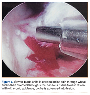
Once the pathologic area is identified, the ultrasonic energy is delivered to the region by the probe, which is activated with a foot pedal, effectively releasing the pathologic tissue from its insertion at the medial tubercle of the calcaneus. The probe is moved in a linear fashion medially and laterally within the lesion across the site of attachment. Treatment continues until the entire soft-tissue lesion is addressed.
Postoperative Care
The wound or wounds are closed with a nylon stitch and Steri-Strip (3M, St. Paul, Minnesota) and covered with Tegaderm (3M) or similar dressing (Figure 7). A compressive dressing is applied. The dressing is removed in 2 to 3 days; the Steri-Strip and stitch are removed in 10 to 14 days. A walking boot is put on immediately after the procedure (most patients in this study already have a boot) and is worn for a few days, or until the symptoms have resolved. How long the boot is used is very much based on patient preference. Patients may continue stretching exercises at home, but there should be no high-impact activity. As-needed ice and analgesics are recommended for the first few days.
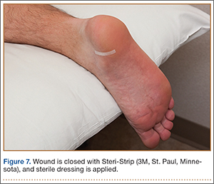
The 12 patients had a mean preoperative AOFAS score of 30 (range, 17-46) and a mean postoperative score of 88 (range, 25-92). By the 3-month postoperative visit, symptoms were resolved in 11 patients (no activity restricted by plantar fascia pain). On physical examination, 11 patients had no palpable tenderness at the site of preoperative pain. Pain relief was documented as having occurred between 5 and 13 weeks after treatment. One patient had bilateral procedures. One foot was treated, pain resolved by the 3-month postoperative visit, and the patient asked for the other foot to be treated. Three months after the second procedure, he had minimal non-activity-restricting pain. There were no postoperative infections or wound complications.
I phoned my patients during postoperative month 24. All 12 patients (13 feet) indicated they were essentially pain-free. None admitted to activity restriction or required over-the-counter pain medication. All indicated they were satisfied with the procedure and would have it again.
The refractory nature of plantar fasciitis, and the resistance to and unpredictability of current treatment options, is well known. Considerable efforts have been made to develop treatment guidelines and algorithms.6 A standard and logical treatment plan involves initial attempts with rest, analgesics, and a walking orthosis and then, if those fail, cortisone or platelet-rich plasma injections. Reluctance to perform surgery is well justified because of the unpredictability of the intervention. As might be expected, the utility of ultrasonography has been on the rise. The diagnostic value of ultrasonography, first recognized in the early 1970s, is of increasing importance.7,8 Subsequent use of ultrasonographic imaging as guidance for various treatments, including percutaneous release, has also been recognized and documented.4,9-12 The present article is the first to describe and document the outcome of using ultrasonic energy for percutaneous release of the diseased attachment of the plantar fascia.
This report is preliminary and was designed to alert the orthopedic community to a safe and promising treatment for a chronic, refractory condition. The safety and efficacy of this treatment are reflected in our experience and have been documented for tennis elbow as well.13
This study was limited by its single-surgeon and relatively small clinical experience. Nevertheless, the benefits of this novel technique—effectiveness, safety, tolerability, and rapid recovery—are encouraging enough to share at this time. Prospective randomized controlled studies are needed.
Conclusion
This is the first report of a plantar fascia partial release guided by ultrasonic energy delivered by a percutaneously inserted probe under local anesthesia. The procedure appears to be a safe, effective, well-tolerated treatment for a condition that is refractory to other options. More studies are needed to further validate the safety and efficacy of this innovative treatment modality.
1. Wall JR, Harkness MA, Crawford A. Ultrasound diagnosis of plantar fasciitis. Foot Ankle. 1993;14(8):465-470.
2. Maffulli N, Regine R, Angelillo M, Capasso G, Filice S. Ultrasound diagnosis of Achilles tendon pathology in runners. Br J Sports Med. 1987;21(4):158-162.
3. Patil P, Dasgupta B. Role of diagnostic ultrasound in the assessment of musculoskeletal diseases. Ther Adv Musculoskelet Dis. 2012;4(5):341-355.
4. Royall NA, Farrin E, Bahner DP, Stawicki SP. Ultrasound-assisted musculoskeletal procedures: a practical overview of current literature. World J Orthop. 2011;2(7):57-66.
5. Tsai WC, Chiu MF, Wang CL, Tang FT, Wong MK. Ultrasound evaluation of plantar fasciitis. Scand J Rheumatol. 2000;29(4):255-259.
6. Thomas JL, Christensen JC, Kravitz SR, et al; American College of Foot and Ankle Surgeons Heel Pain Committee. The diagnosis and treatment of heel pain: a clinical practice guideline—revision 2010. J Foot Ankle Surg. 2010;49(3 suppl):S1-S19.
7. McDonald DG, Leopold GR. Ultrasound B–scanning in the differentiation of Baker’s cyst and thrombophlebitis. Br J Radiol. 1972;45(538):729-732.
8. Blankstein A. Ultrasound in the diagnosis of clinical orthopedics: the orthopedic stethoscope. World J Orthop. 2011;2(2):13-24.
9. Rubens DJ, Fultz PJ, Gottlieb RH, Rubin SJ. Effective ultrasonographically guided intervention for diagnosis of musculoskeletal lesions. J Ultrasound Med. 1997;16(12):831-842.
10. Testa V, Capasso G, Benazzo F, Maffulli N. Management of Achilles tendinopathy by ultrasound-guided percutaneous tenotomy. Med Sci Sports Exerc. 2002;34(4):573-580.
11. Debrule MB. Ultrasound-guided Weil percutaneous plantar fasciotomy. J Am Podiatr Med Assoc. 2010;100(2):146-148.
12. Vohra PK, Japour CJ. Ultrasound-guided plantar fascia release technique: a retrospective study of 46 feet. J Am Podiatr Med Assoc. 2009;99(3):183-190.
13. Koh JS, Mohan PC, Howe TS, et al. Fasciotomy and surgical tenotomy for recalcitrant lateral elbow tendinopathy: early clinical experience with a novel device for minimally invasive percutaneous microresection. Am J Sports Med. 2013;41(3):636-644.
Chronic plantar fasciitis is a major health care problem worldwide and affects nearly 10% of the US population. Plantar fasciitis presents as heel pain in the mornings and usually gets better and then gets worse. Inflammation at the plantar fascia attachment causes acute and sometimes disabling pain. Chronic pain at the site can develop as time goes on because of long-standing inflammatory changes. Fibrotic tissues may develop at the site. On a continuum, symptoms may begin in an insidious phase and progress to chronic pain. Although most cases resolve with conservative care, the numerous treatments for refractory plantar fasciitis attest to the lack of consensus regarding these cases. The condition frustrates patient and physician alike.
Treatments for refractory plantar fasciitis include conservative measures, including rest, analgesics, walking orthosis, heel cup, night splint, walking boot, and then, in a standard and logical progression, cortisone or platelet-rich plasma injections. Improved magnetic resonance imaging and ultrasonographic imaging allow accurate localization of the pathologic process,1-3 and this localization in turn provides an opportunity to deliver a more reliable and focused intervention, as in needle-guided therapy.4 Surgical procedures for plantar fasciitis have included open or endoscopically assisted plantar fasciectomies with or without gastrocnemius recession; these procedures have had varying results. The emerging goals for this condition are a minimally invasive percutaneous intervention that is safe, effective, and well-tolerated and has minimal morbidity and a low complication rate.
We conducted a prospective study in which patients were allowed either to continue with noninvasive treatment or to undergo focal aspiration and partial fasciotomy with an ultrasonic probe. Study inclusion criteria were plantar fasciitis symptoms lasting 12 months or longer. Exclusion criteria were unwillingness to participate in the study. Prior treatments, even surgeries, were not exclusionary.
Twelve patients with refractory plantar fasciitis lasting a mean of 19 months (minimum, 12 months; range, 12-24 months) chose the procedure. They all had failed conservative care, including physical therapy, casting, shockwave therapy, and invasive procedures such as injections and endoscopic partial releases. Four of the 12 had undergone an open or endoscopic partial release at a different institution but had experienced no improvement in symptoms.
Based on the study protocol, patients continued noninvasive care (night splint, stretching exercises) for 2 to 6 weeks after the initial visit. When this conservative care failed, they were offered focal partial fasciectomy with a percutaneous ultrasonic probe. American Orthopaedic Foot and Ankle Society (AOFAS) scores were obtained before and after surgery. Follow-up consisted of clinic visits 2 weeks after surgery and monthly thereafter. I saw all 12 patients 3 months after surgery (range, 11-14 weeks), and all 12 underwent postoperative physical therapy.
Technique
The TX1 Tissue Removal System (Tenex Health, Lake Forest, California) (Figure 1) consists of an energy module, a pump/suction cassette that provides irrigation and suction through a probe, and the probe itself, the TX1, which is the size of an 18-gauge needle and delivers ultrasonic energy. The cassette is inserted into the energy module, and the ultrasonic energy probe is primed so it will deliver the irrigation fluid, normal saline. The safety features of the energy module are such that no energy is expended unless the system is properly irrigating and aspirating the diseased tissue. Ultrasonic treatment may be performed in a clinical or ambulatory surgical center. The patient is placed supine on an operating table, on a clinical examining table, or, if in a cast room, on a cart. A pillow is placed under the distal tibia so the knees can flex slightly, and the patient is positioned so the feet are free of the edge of the bed or gurney (Figure 2).
The pathology is first confirmed by ultrasonography (Figures 3–5). The first step is to identify the calcaneus with the sensor along the long axis of the foot. Then the plantar fascia is visualized and followed along its long axis to the site of attachment at the medial tubercle. As the pathologic process involves the medial site of attachment, a transverse image may also be obtained to better understand the medial/lateral extent of the disease process. The ultrasonographic image of plantar fasciitis has been well characterized.2,5 The pathology is visualized as an area of edema or of disruption of the linear appearance of the fascia as it attaches to the calcaneus. While the diagnosis is being confirmed, the optimal site for probe insertion should be considered based on the location of the pain and the localization of the pathology by the 2 orthogonal images.
The area is prepared as if for an injection and is squared off with sterile towels. Then the sensor is placed in the sterile sleeve. The area of maximum tenderness is again confirmed. Determining the location of the probe insertion site is a crucial step. We use the ultrasonic sensor in the longitudinal and transverse planes to direct the injection of a fast-acting local anesthetic to the medial aspect of the calcaneus. A skin wheal is created, and the fast-acting local anesthetic (3-4 mL) is injected into the region of the fascia pathology.
An 11-blade knife is used to create a site for the probe through the skin wheal at the medial aspect of the heel, in line with the pathology (Figure 6). The probe is then introduced through the puncture site and is identified, along with the pathology, with the sensor, which may be oriented transverse or longitudinal to the long axis of the foot.
Once the pathologic area is identified, the ultrasonic energy is delivered to the region by the probe, which is activated with a foot pedal, effectively releasing the pathologic tissue from its insertion at the medial tubercle of the calcaneus. The probe is moved in a linear fashion medially and laterally within the lesion across the site of attachment. Treatment continues until the entire soft-tissue lesion is addressed.
Postoperative Care
The wound or wounds are closed with a nylon stitch and Steri-Strip (3M, St. Paul, Minnesota) and covered with Tegaderm (3M) or similar dressing (Figure 7). A compressive dressing is applied. The dressing is removed in 2 to 3 days; the Steri-Strip and stitch are removed in 10 to 14 days. A walking boot is put on immediately after the procedure (most patients in this study already have a boot) and is worn for a few days, or until the symptoms have resolved. How long the boot is used is very much based on patient preference. Patients may continue stretching exercises at home, but there should be no high-impact activity. As-needed ice and analgesics are recommended for the first few days.
The 12 patients had a mean preoperative AOFAS score of 30 (range, 17-46) and a mean postoperative score of 88 (range, 25-92). By the 3-month postoperative visit, symptoms were resolved in 11 patients (no activity restricted by plantar fascia pain). On physical examination, 11 patients had no palpable tenderness at the site of preoperative pain. Pain relief was documented as having occurred between 5 and 13 weeks after treatment. One patient had bilateral procedures. One foot was treated, pain resolved by the 3-month postoperative visit, and the patient asked for the other foot to be treated. Three months after the second procedure, he had minimal non-activity-restricting pain. There were no postoperative infections or wound complications.
I phoned my patients during postoperative month 24. All 12 patients (13 feet) indicated they were essentially pain-free. None admitted to activity restriction or required over-the-counter pain medication. All indicated they were satisfied with the procedure and would have it again.
The refractory nature of plantar fasciitis, and the resistance to and unpredictability of current treatment options, is well known. Considerable efforts have been made to develop treatment guidelines and algorithms.6 A standard and logical treatment plan involves initial attempts with rest, analgesics, and a walking orthosis and then, if those fail, cortisone or platelet-rich plasma injections. Reluctance to perform surgery is well justified because of the unpredictability of the intervention. As might be expected, the utility of ultrasonography has been on the rise. The diagnostic value of ultrasonography, first recognized in the early 1970s, is of increasing importance.7,8 Subsequent use of ultrasonographic imaging as guidance for various treatments, including percutaneous release, has also been recognized and documented.4,9-12 The present article is the first to describe and document the outcome of using ultrasonic energy for percutaneous release of the diseased attachment of the plantar fascia.
This report is preliminary and was designed to alert the orthopedic community to a safe and promising treatment for a chronic, refractory condition. The safety and efficacy of this treatment are reflected in our experience and have been documented for tennis elbow as well.13
This study was limited by its single-surgeon and relatively small clinical experience. Nevertheless, the benefits of this novel technique—effectiveness, safety, tolerability, and rapid recovery—are encouraging enough to share at this time. Prospective randomized controlled studies are needed.
Conclusion
This is the first report of a plantar fascia partial release guided by ultrasonic energy delivered by a percutaneously inserted probe under local anesthesia. The procedure appears to be a safe, effective, well-tolerated treatment for a condition that is refractory to other options. More studies are needed to further validate the safety and efficacy of this innovative treatment modality.
1. Wall JR, Harkness MA, Crawford A. Ultrasound diagnosis of plantar fasciitis. Foot Ankle. 1993;14(8):465-470.
2. Maffulli N, Regine R, Angelillo M, Capasso G, Filice S. Ultrasound diagnosis of Achilles tendon pathology in runners. Br J Sports Med. 1987;21(4):158-162.
3. Patil P, Dasgupta B. Role of diagnostic ultrasound in the assessment of musculoskeletal diseases. Ther Adv Musculoskelet Dis. 2012;4(5):341-355.
4. Royall NA, Farrin E, Bahner DP, Stawicki SP. Ultrasound-assisted musculoskeletal procedures: a practical overview of current literature. World J Orthop. 2011;2(7):57-66.
5. Tsai WC, Chiu MF, Wang CL, Tang FT, Wong MK. Ultrasound evaluation of plantar fasciitis. Scand J Rheumatol. 2000;29(4):255-259.
6. Thomas JL, Christensen JC, Kravitz SR, et al; American College of Foot and Ankle Surgeons Heel Pain Committee. The diagnosis and treatment of heel pain: a clinical practice guideline—revision 2010. J Foot Ankle Surg. 2010;49(3 suppl):S1-S19.
7. McDonald DG, Leopold GR. Ultrasound B–scanning in the differentiation of Baker’s cyst and thrombophlebitis. Br J Radiol. 1972;45(538):729-732.
8. Blankstein A. Ultrasound in the diagnosis of clinical orthopedics: the orthopedic stethoscope. World J Orthop. 2011;2(2):13-24.
9. Rubens DJ, Fultz PJ, Gottlieb RH, Rubin SJ. Effective ultrasonographically guided intervention for diagnosis of musculoskeletal lesions. J Ultrasound Med. 1997;16(12):831-842.
10. Testa V, Capasso G, Benazzo F, Maffulli N. Management of Achilles tendinopathy by ultrasound-guided percutaneous tenotomy. Med Sci Sports Exerc. 2002;34(4):573-580.
11. Debrule MB. Ultrasound-guided Weil percutaneous plantar fasciotomy. J Am Podiatr Med Assoc. 2010;100(2):146-148.
12. Vohra PK, Japour CJ. Ultrasound-guided plantar fascia release technique: a retrospective study of 46 feet. J Am Podiatr Med Assoc. 2009;99(3):183-190.
13. Koh JS, Mohan PC, Howe TS, et al. Fasciotomy and surgical tenotomy for recalcitrant lateral elbow tendinopathy: early clinical experience with a novel device for minimally invasive percutaneous microresection. Am J Sports Med. 2013;41(3):636-644.
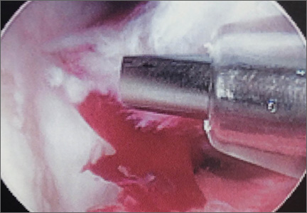
Antibiotic Cement-Coated Plates for Management of Infected Fractures
Deep infection in the presence of an implant after open reduction and internal fixation (ORIF) is usually treated with removal of the implant, serial débridement procedures, lavage, intravenously administered antibiotics, and, in some cases, placement of antibiotic-impregnated beads. If infection occurs during the early stages of bone healing, stabilization of the fractures might be compromised after removal of the implant. Although antibiotic-impregnated beads offer local delivery of antibiotics, they do not provide structural support of the fracture site. The beads often are difficult to remove after in-growth of granulation tissue. In areas of subcutaneous bone, an antibiotic bead pouch might be preferred to an open wound. Published research regarding the use of antibiotic-coated plates during the acute or chronic stages of infection is scarce. Plates offer the versatility of fracture stabilization, and the addition of antibiotic cement to the plates might aid in eradication of infection without necessitating a second surgery for removal. The patients provided written informed consent for print and electronic publication of these case reports.
Technique
After removal of implants, we perform débridement of the soft tissues with a hydroscalpel (Versajet; Smith & Nephew, London, United Kingdom), mechanical débridement of bone, and curettage with high speed burr. The wound is then irrigated with pulse pressure lavage and a minimum of 3 L sterile normal saline. The extremity is re-prepped and re-draped; the entire surgical team’s gowns and gloves are changed; and new instrumentation, including cautery and suction equipment, is used. The cement is prepared with tobramycin (3.6 g) and vancomycin (1 g) per 40-g bag of cement. The plate is placed in silicon tubing, and the antibiotic-prepared cement is injected into the tubing and molded until dry. Care is taken to mold the locations of the screw holes by making incisions in the tubing at the appropriate locations. Screws are placed through the screw holes to ensure locking capability, and Kirschner wires are placed through temporary fixation holes (Figure 1). Once dry, the screws and wires are removed from the plate, and the cement-coated plate is removed from the tubing. The antibiotic-coated plate is applied to the fracture or osteotomy site and is seated with screws as appropriate (Figure 2). The wound is closed primarily. Wound drains or vacuum-assisted closure devices are not routinely used unless there is high risk for hematoma formation. The authors prefer to have high local concentrations of antibiotic in the surrounding tissues and wound.
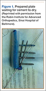
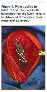
Clinical Series
Case 1
A 31-year-old man fell from a ladder and sustained a bimalleolar ankle fracture-dislocation that was treated with ORIF. Three weeks after initial injury, the patient presented with an infected lateral wound with purulent discharge. He was taken to the operating room for initial débridement, irrigation, and fracture stabilization with an antibiotic-coated plate and tension-band wiring of the medial malleoli. He was discharged from the hospital on day 4 after admission. Cultures of the wound grew beta-hemolytic strep group G and coagulase-negative staphylococci in broth that was sensitive to oxacillin, vancomycin, and gentamycin. The patient was treated with a 6-week regimen of Unasyn (Roerig, New York, New York), developed bony union, and has been free of clinical signs of infection for 2 years (Figures 3, 4).
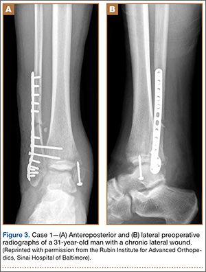
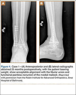
Case 2
A 27-year-old male carpenter fell from a height of 12 feet and sustained a fracture of the distal radius that was treated with external fixation. The proximal pin site became clinically infected and subsequently developed osteomyelitis. The patient had a draining wound with a fracture for 2 months. He underwent débridement with partial resection of the radius and placement of an antibiotic cement–coated plate and calcium phosphate bone-void filler impregnated with antibiotics. Pathology specimens were positive for osteomyelitis, and bone cultures showed methicillin-sensitive Staphylococcus aureus (MSSA). He received intravenously administered antibiotic therapy for 6 weeks after surgery. The patient has remained free of clinical signs of infection for more than 1 year and has achieved bony union (Figures 5A, 5B).
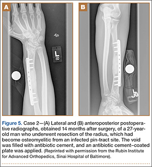
Case 3
A 44-year-old woman with insulin-dependent diabetes mellitus and venous stasis sustained a trimalleolar ankle fracture after a low-energy fall that was initially treated with ORIF. She underwent revision ORIF to treat a malunion 3 months after initial treatment. At 8 months, the patient developed a draining sinus communicating with the plate. Computed tomography revealed nonunion and indicated infection. The patient underwent resection of the osteomyelitis and repair of the fibular nonunion with an antibiotic-coated plate. Tissue cultures were positive for coagulase-negative staphylococcus, and pathology specimens were positive for osteomyelitis. She received postoperative antibiotics intravenously and 6 weeks of antibiotic therapy after discharge from the hospital. The patient has remained free of clinical signs of infection for more than 1 year and has achieved bony union (Figures 6, 7).
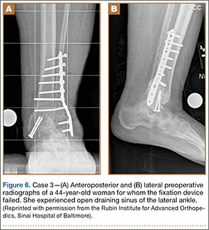
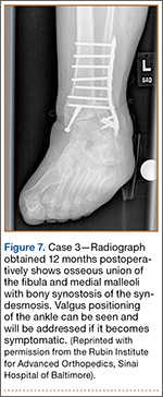
Case 4
A 48-year-old man sustained an open olecranon fracture in another country. The fracture was initially treated with 1 dose of intravenously administered antibiotics and 5 days of orally administered antibiotics. The patient returned to the United States and was treated with intravenously administered antibiotics for cellulitis of the elbow for 11 days before referral to our institution, where he underwent ORIF with placement of an antibiotic-coated plate and tension-band wiring. Soft-tissue and bone cultures had no growth. He received intravenously administered antibiotics for 6 weeks. At 5 months postoperatively, the plate was removed because of pain. The patient has remained free of clinical signs of infection for more than 1 year and has achieved bony union (Figures 8A-8C).
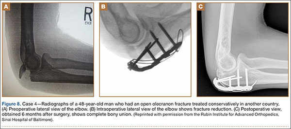
Discussion
Acute infections of fractures have recently been treated with success by Berkes and colleagues,1 who reported a 71% union rate achieved with operative débridement, antibiotic suppression, and retention of fixation until fracture union occurs. The study by Berkes and colleagues1 had a small patient population, and larger cohorts are needed to show more reliable results; however, this treatment maintains structural support for the fracture during healing but requires multiple trips to the operating room for débridements as well as the use of systemic intravenous antibiotic therapy.
A technique that was developed by the primary author (Janet D. Conway, MD) and has not been described in the literature allows for use of antibiotic cement–coated plates to treat early postoperative infections and osteomyelitic nonunions. This approach permits fracture stabilization and local delivery of high concentrations of broad-spectrum antibiotics and can reduce the number of débridement procedures required in the operating room. We present a technique that includes the use of antibiotic cement–coated plates to treat early postoperative infections associated with fractures and nonunions in order to provide eradication of infection and bony stabilization.
Our approach parallels the current theory that treating infection at a site of union is preferable to treating infection at a site of nonunion.1 Fixation devices should remain in place until osseous union is achieved. With the addition of antibiotics to the plate, removal might not be necessary unless a device is loose, nonfunctional, or, ultimately, causing pain. Other options, such as external fixation, can be burdensome to patients and can be associated with other risks. One of our 4 patients required fixation removal because of pain at the elbow; however, even noncoated olecranon plates typically are removed because of pain after fracture healing. Antibiotic cement adds bulk to the construct and can become very prominent in areas of little soft-tissue coverage (Figure 9).
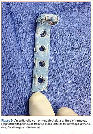
Studies, assessing variables that correlate with higher likelihood of failure for primary repairs, have shown that open fracture, use of an intramedullary nail, and smoking are the highest risk factors for infected nonunion.1−4 Among our 4 patients, 3 were smokers and 1 originally had an open fracture. Smokers have been found to have a 37% higher nonunion rate and are 2 times more likely to develop wound infection and osteomyelitis.1,5 More than 60% of the time, infections are caused by S aureus or coagulase-negative staphylococci.1,5,6 In our study population, 3 of the 4 patients had coagulase-negative staphylococci grow in the cultures. Implants infected with S aureus or Candida require surgical removal. Those with less virulent coagulase-negative staphylococci might not necessitate removal; however, our population had had antibiotic therapy and continued draining sinus.5 Rightmire and colleagues7 reported that those who develop infection earlier than 16 weeks postoperatively have a 68% success rate and that smoking is a major risk factor for infection. Development of Pseudomonas in the wound has been shown to have a positive correlation with amputation.1,2 Infection with Pseudomonas, smoking, and involvement of the femur, tibia, ankle, or foot tended to result in failure.1,2 Being clinically free of signs of infection after 3 months offers a 50% cure rate, with 78% at 6 months and 95% after 1 year.2
When determining an antibiotic to use with the polymethylmethacrylate (PMMA) cement, many factors must be considered, including spectrum, heat stability, and elution characteristics.8 A synergistic effect has been seen with combinations of antibiotics (eg, vancomycin and tobramycin used together). Vancomycin concentrations increased by 103% and tobramycin by 68% when used together compared with their elution rates when used alone, showing passive opportunism.9 This will, in essence, increase concentrations of antibiotics at the site locally, which will increase the bacteriocidal potential but also create a larger antimicrobial spectrum.9
The authors used Cobalt Bone Cement (Biomet Orthopedics, Inc, Warsaw, Indiana) which been shown to have higher elution properties than Simplex P Bone Cement (Stryker, Kalamazoo, Michigan).3,10 The majority of elution occurs in the first 3 to 5 days but can continue for weeks after implantation. We place the cement on the plate allowing for its retention, hoping to eliminate a second surgery for removal.8 We recommend 3.6 g of tobramycin, and 1 g of vancomycin per 40-g bag of PMMA.3 This dose has been shown to be safe in respect to renal toxicity, plus the entire dose is not administered in a single setting because only a small portion of the cement is used when coating the plate. We close all wounds primarily, and do not regularly use drains or vacuum-assisted closures to help prevent a decrease in the local concentration of the antibiotics.11
Broad-spectrum antibiotics are used to coat the plate in order to cover as many microbial organisms as possible without knowing the final offending organism. In our experience, this current technique provides antibiotic delivery with bony stability, therefore eliminating the need for multiple sequential surgical procedures. This difficult patient problem does not occur with enough frequency to warrant a large randomized clinical trial. However, this technique has been effective in these cases and may be useful to orthopedic surgeons in the future.
Conclusion
Based on our experience, early aggressive débridement, coupled with broad-spectrum antibiotic cement–coated plate insertion, provides fracture stability and helps eradicate the infection with 1 surgical procedure.
1. Berkes M, Obremskey WT, Scannell B, et al. Maintenance of hardware after early postoperative infection following fracture internal fixation. J Bone Joint Surg Am. 2010;92(4):823-828.
2. Tice AD, Hoaglund PA, Shoultz, DA. Risk factors and treatment outcomes in osteomyelitis. J Antimicrob Chemother. 2003;51(5):1261-1268.
3. Patzakis MJ, Zalavras CG. Chronic posttraumatic osteomyelitis and infected nonunion of the tibia: current management concepts. J Am Acad Orthop Surg. 2005;13(6):417-427.
4. Castillo RC, Bosse MJ, MacKenzie EJ, Patterson BM; LEAP Study Group. Impact of smoking on fracture healing and risk of complications in limb-threatening open tibia fractures. J Orthop Trauma. 2005;19(3):151-157.
5. Liporace FA, Yoon RS, Frank MA, et al. Use of an “antibiotic plate” for infected periprosthetic fracture in total hip arthroplasty. J Orthop Trauma. 2012;26(3):e18-e23.
6. Darouiche RO. Treatment of infections associated with surgical implants. N Engl J Med. 2004;350(14):1422-1429.
7. Rightmire E, Zurakowski D, Vrahas M. Acute infections after fracture repair: management with hardware in place. Clin Orthop. 2008;466(2):466-472.
8. Adams K, Couch L, Cierny G, Calhoun J, Mader JT. In vitro and in vivo evaluation of antibiotic diffusion from antibiotic-impregnated polymethylmethacrylate beads. Clin Orthop. 1992;(278):244-252.
9. Penner MJ, Masri BA, Duncan CP. Elution characteristics of vancomycin and tobramycin combined in acrylic bone-cement. J Arthroplasty. 1996;11(8):939-944.
10. Greene N, Holtom PD, Warren CA, et al. In vitro elution of tobramycin and vancomycin polymethylmethacrylate beads and spacers from Simplex and Palacos. Am J Orthop. 1998;27(3):201-205.
11. Kalil GZ, Ernst EJ, Johnson SJ, et al. Systemic exposure to aminoglycosides following knee and hip arthroplasty with aminoglycoside-loaded bone cement implants. Ann Pharmacother. 2012;46(7-8):929-934.
Deep infection in the presence of an implant after open reduction and internal fixation (ORIF) is usually treated with removal of the implant, serial débridement procedures, lavage, intravenously administered antibiotics, and, in some cases, placement of antibiotic-impregnated beads. If infection occurs during the early stages of bone healing, stabilization of the fractures might be compromised after removal of the implant. Although antibiotic-impregnated beads offer local delivery of antibiotics, they do not provide structural support of the fracture site. The beads often are difficult to remove after in-growth of granulation tissue. In areas of subcutaneous bone, an antibiotic bead pouch might be preferred to an open wound. Published research regarding the use of antibiotic-coated plates during the acute or chronic stages of infection is scarce. Plates offer the versatility of fracture stabilization, and the addition of antibiotic cement to the plates might aid in eradication of infection without necessitating a second surgery for removal. The patients provided written informed consent for print and electronic publication of these case reports.
Technique
After removal of implants, we perform débridement of the soft tissues with a hydroscalpel (Versajet; Smith & Nephew, London, United Kingdom), mechanical débridement of bone, and curettage with high speed burr. The wound is then irrigated with pulse pressure lavage and a minimum of 3 L sterile normal saline. The extremity is re-prepped and re-draped; the entire surgical team’s gowns and gloves are changed; and new instrumentation, including cautery and suction equipment, is used. The cement is prepared with tobramycin (3.6 g) and vancomycin (1 g) per 40-g bag of cement. The plate is placed in silicon tubing, and the antibiotic-prepared cement is injected into the tubing and molded until dry. Care is taken to mold the locations of the screw holes by making incisions in the tubing at the appropriate locations. Screws are placed through the screw holes to ensure locking capability, and Kirschner wires are placed through temporary fixation holes (Figure 1). Once dry, the screws and wires are removed from the plate, and the cement-coated plate is removed from the tubing. The antibiotic-coated plate is applied to the fracture or osteotomy site and is seated with screws as appropriate (Figure 2). The wound is closed primarily. Wound drains or vacuum-assisted closure devices are not routinely used unless there is high risk for hematoma formation. The authors prefer to have high local concentrations of antibiotic in the surrounding tissues and wound.
Clinical Series
Case 1
A 31-year-old man fell from a ladder and sustained a bimalleolar ankle fracture-dislocation that was treated with ORIF. Three weeks after initial injury, the patient presented with an infected lateral wound with purulent discharge. He was taken to the operating room for initial débridement, irrigation, and fracture stabilization with an antibiotic-coated plate and tension-band wiring of the medial malleoli. He was discharged from the hospital on day 4 after admission. Cultures of the wound grew beta-hemolytic strep group G and coagulase-negative staphylococci in broth that was sensitive to oxacillin, vancomycin, and gentamycin. The patient was treated with a 6-week regimen of Unasyn (Roerig, New York, New York), developed bony union, and has been free of clinical signs of infection for 2 years (Figures 3, 4).
Case 2
A 27-year-old male carpenter fell from a height of 12 feet and sustained a fracture of the distal radius that was treated with external fixation. The proximal pin site became clinically infected and subsequently developed osteomyelitis. The patient had a draining wound with a fracture for 2 months. He underwent débridement with partial resection of the radius and placement of an antibiotic cement–coated plate and calcium phosphate bone-void filler impregnated with antibiotics. Pathology specimens were positive for osteomyelitis, and bone cultures showed methicillin-sensitive Staphylococcus aureus (MSSA). He received intravenously administered antibiotic therapy for 6 weeks after surgery. The patient has remained free of clinical signs of infection for more than 1 year and has achieved bony union (Figures 5A, 5B).
Case 3
A 44-year-old woman with insulin-dependent diabetes mellitus and venous stasis sustained a trimalleolar ankle fracture after a low-energy fall that was initially treated with ORIF. She underwent revision ORIF to treat a malunion 3 months after initial treatment. At 8 months, the patient developed a draining sinus communicating with the plate. Computed tomography revealed nonunion and indicated infection. The patient underwent resection of the osteomyelitis and repair of the fibular nonunion with an antibiotic-coated plate. Tissue cultures were positive for coagulase-negative staphylococcus, and pathology specimens were positive for osteomyelitis. She received postoperative antibiotics intravenously and 6 weeks of antibiotic therapy after discharge from the hospital. The patient has remained free of clinical signs of infection for more than 1 year and has achieved bony union (Figures 6, 7).
Case 4
A 48-year-old man sustained an open olecranon fracture in another country. The fracture was initially treated with 1 dose of intravenously administered antibiotics and 5 days of orally administered antibiotics. The patient returned to the United States and was treated with intravenously administered antibiotics for cellulitis of the elbow for 11 days before referral to our institution, where he underwent ORIF with placement of an antibiotic-coated plate and tension-band wiring. Soft-tissue and bone cultures had no growth. He received intravenously administered antibiotics for 6 weeks. At 5 months postoperatively, the plate was removed because of pain. The patient has remained free of clinical signs of infection for more than 1 year and has achieved bony union (Figures 8A-8C).
Discussion
Acute infections of fractures have recently been treated with success by Berkes and colleagues,1 who reported a 71% union rate achieved with operative débridement, antibiotic suppression, and retention of fixation until fracture union occurs. The study by Berkes and colleagues1 had a small patient population, and larger cohorts are needed to show more reliable results; however, this treatment maintains structural support for the fracture during healing but requires multiple trips to the operating room for débridements as well as the use of systemic intravenous antibiotic therapy.
A technique that was developed by the primary author (Janet D. Conway, MD) and has not been described in the literature allows for use of antibiotic cement–coated plates to treat early postoperative infections and osteomyelitic nonunions. This approach permits fracture stabilization and local delivery of high concentrations of broad-spectrum antibiotics and can reduce the number of débridement procedures required in the operating room. We present a technique that includes the use of antibiotic cement–coated plates to treat early postoperative infections associated with fractures and nonunions in order to provide eradication of infection and bony stabilization.
Our approach parallels the current theory that treating infection at a site of union is preferable to treating infection at a site of nonunion.1 Fixation devices should remain in place until osseous union is achieved. With the addition of antibiotics to the plate, removal might not be necessary unless a device is loose, nonfunctional, or, ultimately, causing pain. Other options, such as external fixation, can be burdensome to patients and can be associated with other risks. One of our 4 patients required fixation removal because of pain at the elbow; however, even noncoated olecranon plates typically are removed because of pain after fracture healing. Antibiotic cement adds bulk to the construct and can become very prominent in areas of little soft-tissue coverage (Figure 9).
Studies, assessing variables that correlate with higher likelihood of failure for primary repairs, have shown that open fracture, use of an intramedullary nail, and smoking are the highest risk factors for infected nonunion.1−4 Among our 4 patients, 3 were smokers and 1 originally had an open fracture. Smokers have been found to have a 37% higher nonunion rate and are 2 times more likely to develop wound infection and osteomyelitis.1,5 More than 60% of the time, infections are caused by S aureus or coagulase-negative staphylococci.1,5,6 In our study population, 3 of the 4 patients had coagulase-negative staphylococci grow in the cultures. Implants infected with S aureus or Candida require surgical removal. Those with less virulent coagulase-negative staphylococci might not necessitate removal; however, our population had had antibiotic therapy and continued draining sinus.5 Rightmire and colleagues7 reported that those who develop infection earlier than 16 weeks postoperatively have a 68% success rate and that smoking is a major risk factor for infection. Development of Pseudomonas in the wound has been shown to have a positive correlation with amputation.1,2 Infection with Pseudomonas, smoking, and involvement of the femur, tibia, ankle, or foot tended to result in failure.1,2 Being clinically free of signs of infection after 3 months offers a 50% cure rate, with 78% at 6 months and 95% after 1 year.2
When determining an antibiotic to use with the polymethylmethacrylate (PMMA) cement, many factors must be considered, including spectrum, heat stability, and elution characteristics.8 A synergistic effect has been seen with combinations of antibiotics (eg, vancomycin and tobramycin used together). Vancomycin concentrations increased by 103% and tobramycin by 68% when used together compared with their elution rates when used alone, showing passive opportunism.9 This will, in essence, increase concentrations of antibiotics at the site locally, which will increase the bacteriocidal potential but also create a larger antimicrobial spectrum.9
The authors used Cobalt Bone Cement (Biomet Orthopedics, Inc, Warsaw, Indiana) which been shown to have higher elution properties than Simplex P Bone Cement (Stryker, Kalamazoo, Michigan).3,10 The majority of elution occurs in the first 3 to 5 days but can continue for weeks after implantation. We place the cement on the plate allowing for its retention, hoping to eliminate a second surgery for removal.8 We recommend 3.6 g of tobramycin, and 1 g of vancomycin per 40-g bag of PMMA.3 This dose has been shown to be safe in respect to renal toxicity, plus the entire dose is not administered in a single setting because only a small portion of the cement is used when coating the plate. We close all wounds primarily, and do not regularly use drains or vacuum-assisted closures to help prevent a decrease in the local concentration of the antibiotics.11
Broad-spectrum antibiotics are used to coat the plate in order to cover as many microbial organisms as possible without knowing the final offending organism. In our experience, this current technique provides antibiotic delivery with bony stability, therefore eliminating the need for multiple sequential surgical procedures. This difficult patient problem does not occur with enough frequency to warrant a large randomized clinical trial. However, this technique has been effective in these cases and may be useful to orthopedic surgeons in the future.
Conclusion
Based on our experience, early aggressive débridement, coupled with broad-spectrum antibiotic cement–coated plate insertion, provides fracture stability and helps eradicate the infection with 1 surgical procedure.
1. Berkes M, Obremskey WT, Scannell B, et al. Maintenance of hardware after early postoperative infection following fracture internal fixation. J Bone Joint Surg Am. 2010;92(4):823-828.
2. Tice AD, Hoaglund PA, Shoultz, DA. Risk factors and treatment outcomes in osteomyelitis. J Antimicrob Chemother. 2003;51(5):1261-1268.
3. Patzakis MJ, Zalavras CG. Chronic posttraumatic osteomyelitis and infected nonunion of the tibia: current management concepts. J Am Acad Orthop Surg. 2005;13(6):417-427.
4. Castillo RC, Bosse MJ, MacKenzie EJ, Patterson BM; LEAP Study Group. Impact of smoking on fracture healing and risk of complications in limb-threatening open tibia fractures. J Orthop Trauma. 2005;19(3):151-157.
5. Liporace FA, Yoon RS, Frank MA, et al. Use of an “antibiotic plate” for infected periprosthetic fracture in total hip arthroplasty. J Orthop Trauma. 2012;26(3):e18-e23.
6. Darouiche RO. Treatment of infections associated with surgical implants. N Engl J Med. 2004;350(14):1422-1429.
7. Rightmire E, Zurakowski D, Vrahas M. Acute infections after fracture repair: management with hardware in place. Clin Orthop. 2008;466(2):466-472.
8. Adams K, Couch L, Cierny G, Calhoun J, Mader JT. In vitro and in vivo evaluation of antibiotic diffusion from antibiotic-impregnated polymethylmethacrylate beads. Clin Orthop. 1992;(278):244-252.
9. Penner MJ, Masri BA, Duncan CP. Elution characteristics of vancomycin and tobramycin combined in acrylic bone-cement. J Arthroplasty. 1996;11(8):939-944.
10. Greene N, Holtom PD, Warren CA, et al. In vitro elution of tobramycin and vancomycin polymethylmethacrylate beads and spacers from Simplex and Palacos. Am J Orthop. 1998;27(3):201-205.
11. Kalil GZ, Ernst EJ, Johnson SJ, et al. Systemic exposure to aminoglycosides following knee and hip arthroplasty with aminoglycoside-loaded bone cement implants. Ann Pharmacother. 2012;46(7-8):929-934.
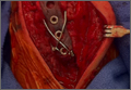
Printable Guide on the Rosacea Patient Journey
The Rosacea Patient Journey: A Novel Approach to Conceptualizing Patient Experiences
Rosacea patients experience symptoms ranging from flushing to persistent acnelike rashes that can cause low self-esteem and anxiety, leading to social and professional isolation.1 Although it is estimated that 16 million individuals in the United States have rosacea, only 10% seek treatment.2,3 The motivation for patients to seek and adhere to treatment is not well characterized.
A patient journey is a map of the steps a patient takes as he/she progresses through different segments of the disease from diagnosis to management, including all the influences that can push him/her toward or away from certain decisions. The patient journey model provides a structure for understanding key issues in rosacea management, including barriers to successful treatment outcomes.
The patient journey model progresses from development of disease and diagnosis to treatment and disease management (Figure). We sought to examine each step of the rosacea patient journey to better understand key patient care boundaries faced by rosacea patients. We assessed the current literature regarding each step of the patient experience and identified areas of the patient journey with limited research.
Click here to view the figure as a PDF to print for future reference.
Researching the Patient Experience
A PubMed search of articles indexed for MEDLINE as well as a search of the National Rosacea Society Web site (http://www.rosacea.org) were conducted to identify articles and materials that quantitatively or qualitatively described rosacea patient experiences. Search terms included rosacea, rosacea patient experience, rosacea treatment, rosacea adherence, and rosacea quality of life. A Google search also was conducted using the same terms to obtain current news articles online. Current literature pertaining to the patient journey was summarized.
To create a model for the rosacea patient journey, we refined a rheumatoid arthritis patient journey map4 and included the critical components of the journey for rosacea patients. We organized the journey into stages, including prediagnosis, diagnosis, treatment, adherence, and management. We first explored what occurs prior to diagnosis, which includes the patient’s symptoms before visiting a physician. We then examined the process of diagnosis and the implementation of a treatment plan. Treatment adherence was then explored, ending with the ways patients self-manage their disease beyond the physician’s office.
Prediagnosis: What Motivates Patients to Seek Treatment
Rosacea can present with many symptoms that may lead patients to see a physician, including facial erythema and telangiectases, papules and pustules, phymatous changes, and ocular manifestations.5 The most common concern is temporary facial flushing, followed by persistent redness, then bumps and pimples.6 Many patients seek treatment after persistent facial flushing and an intolerable burning sensation. Some middle-aged patients decide to see a dermatologist for the first time when they break out in acne lesions after a history of clear skin. Others seek treatment because they can no longer tolerate the pain and embarrassment associated with their symptoms. However, patients who seek treatment only account for a small proportion of patients with rosacea, as only 10% of patients seek conventional medical treatment.7 Furthermore, symptomatic patients on average wait 7 months to 5 years before receiving a diagnosis.8,9
Care often is delayed or not pursued because many rosacea symptoms are mild when they first appear and may not initially bother the patient. Patients may not think anything of their symptoms and dismiss them as either acne vulgaris or sunburn. Due to the relapsing and remitting nature of the disease course, patients may feel their symptoms will resolve. Of patients diagnosed with rosacea, only one-half have heard of the condition prior to diagnosis,8 which can largely be attributed to lack of patient education on the signs and symptoms of rosacea, a concern that prompted the National Rosacea Society to designate the month of April as rosacea awareness month.5
With sales of antiredness facial care products growing 35% from 2002 to 2007, accounting for an increase of $300 million in revenue, patients also may be turning to over-the-counter products first.10 Men with rosacea tend to present with more severe symptoms such as rhinophyma, which may be due to their desire to wait until their symptoms reached more advanced stages of disease before seeking medical help.5
Diagnosis of Rosacea
After the patient decides that his/her symptoms are unusual, severe, or intolerable enough to seek treatment, the issues of access to dermatologic care and receiving the correct diagnosis come into play. Accessing dermatologic care can be difficult, as appointments may be hard to obtain, and even if the patient is able to get an appointment, it could be many weeks later.11 For some rosacea patients, the anxiety of waiting for their appointment prompts them to seek support and advice from online message boards (eg, http://www.rosacea-support.org). The long wait for appointments may be attributed to the increased demand for dermatologists for cosmetic procedures.12 Additionally, disparities according to insurance type can contribute to difficulties procuring an appointment. In one study, privately insured dermatology patients demonstrated a 91% acceptance rate and shorter wait times for appointments compared to publicly insured patients who were limited to a 29.8% acceptance rate and longer wait times.11 Many patients then are left to wait for an appointment with a dermatologist or instead turn to a primary care physician. Of patients diagnosed with rosacea in one study (N=2847), the majority of patients were seen by a dermatologist (79%), while the other patients were diagnosed by a family physician (14%) or other types of physicians such as internists and ophthalmologists (7%).6
The diagnosis of rosacea usually is not a major hurdle for dermatologists, but misdiagnoses can sometimes occur. The Rosacea Research & Development Institute compiled multiple patient anecdotes describing the struggles of finally reaching the correct diagnosis of rosacea; however, no estimates as to the frequency of misdiagnoses was estimated.13 Even with an accurate diagnosis of rosacea, correct classification of the 4 types of rosacea (ie, erythematotelangiectatic, papulopustular, phymatous, ocular) is necessary to avoid incorrect treatment recommendations. For example, patients with flushing often cannot tolerate topical medications in contrast to patients with the papulopustular subtype who benefit from them.14 In the meantime, the patients who are misdiagnosed may be met with frustration, as treatment was either delayed or incorrectly prescribed.
Although there are limited data regarding patient reactions after receiving a diagnosis of rosacea, it can be assumed that patients would be hopeful that diagnosis would lead to correct treatment. In a 2008 article in The New York Times, a rosacea patient was described as feeling relieved to be diagnosed with rosacea because it was an explanation for the development of pimples on the cheeks in her late 40s.10
Implementation of a Treatment Plan
After recognizing the symptoms and receiving a correct diagnosis, the next step in the patient journey is treatment. Long-term management of incurable conditions such as rosacea is difficult. The main goals of treatment are to relieve symptoms, improve appearance, delay progression to advanced stages, and maintain remission.15 There are only a few reliable clinical trials regarding therapies for rosacea, so treatment has mostly relied on clinical experience (Table). The efficacy and safety of many older treatments has not been assessed.15 Mainstays of treatment include both topical agents and oral medications. The use of topical metronidazole, oral tetracycline, and oral isotretinoin have been found to improve both skin lesions and quality of life.18 Initially, a combination of a topical and an oral medication may be used for at least the first 12 weeks, and improvement is usually gradual, taking many weeks to become evident.15 Long-term treatment with topical medications often is required for maintenance, which can last another 6 months or more.19,20
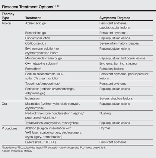
Besides using pharmacologic therapies, some patients also may choose to undergo various procedures. The most common procedure is laser therapy, followed by dermabrasion, chemical peels, hot loop electrocoagulation, and surgical sculpting or plastic surgery.6 The use of these adjunct therapies may suggest impatience from the patient for improvement; it also indicates the lengths patients will go to and willingness to pay for improvement of symptoms.
Along with medication, patients are recommended to make changes to their skin care regimen and lifestyle. Rosacea patients typically have sensitive skin that may include symptoms such as dryness, scaling, stinging, burning, and pruritus.16 Skin care recommendations for rosacea patients include using a gentle cleanser and regularly applying sunscreen.5 Issues with physical appearance can be addressed with the use of cosmetic products such as green-tinted makeup to conceal skin lesions.21 Remission can be maintained by identifying certain triggers (eg, red wine, spicy foods, extreme temperatures, prolonged sun exposure, vigorous exercise) that can cause flare-ups.15 The most common trigger is sun exposure, making photoprotection an important component of the rosacea patient’s skin care regimen.6
Adherence
With a diagnosis and treatment plan in effect, the patient journey reaches the stage of treatment adherence, which should include ongoing education about the condition. Self-reported statistics from rosacea patients indicated that 28% of patients took time off from their treatment regimen,6 but actual nonadherence rates likely are higher. The most commonly reported reason for poor treatment adherence among rosacea patients was the impression that the symptoms had resolved or were adequately controlled.6 Treatment also must be affordable. In a national survey of rosacea patients, 24% of 427 patients receiving pharmacologic therapy planned on switching medications because of cost, and 17% of 769 patients discontinued medications due to co-pay/insurance issues.6 Other reasons cited for discontinuation of treatment included patient perception that symptoms were not that serious, co-pay/insurance issues, ineffectiveness of the medication, and side effects.6 Adherence to topical medications is lower than oral medications due to the time and inconvenience required for application.22 For some patients, topical medications may be too messy, have a strange odor, or stain clothing.
It is promising that most rosacea patients have reported the intent to continue using pharmacologic agents because the medication prevented worsening of their symptoms.6 However, there are still patients who switch or discontinue therapies without physician direction. These patients often cite that they desire more information at the time of diagnosis, particularly related to causes of flare-ups, physical symptoms to expect, drug treatment options, makeup to cover up visible symptoms, surgical or laser treatment options, psychological symptoms, patient support groups, and counseling options.6
Management
The last part of the journey is disease management, which occurs when the patient learns how to control his/her symptoms long-term. Important factors contributing to long-term control of rosacea flares are medication adherence and avoiding lifestyle triggers.23,24 Through the other stages of the journey, the patient has learned which treatments work and which factors may lead to exacerbation of symptoms.
Educating Patients on the Journey
The patient journey is a concept that can be applied to any disease state and brings to light roadblocks that patients may face from the initial diagnosis to successful disease management. Rosacea patients are faced with confusing and aggravating symptoms that can cause anxiety and may lead them to seek treatment from a physician. Facial flushing and phymatous changes of the nose can be mistaken for alcohol abuse, leading rosacea to be a socially stigmatizing disease.15 Because rosacea involves mostly the facial skin, it can disrupt social and professional interactions, leading to quality-of-life effects such as difficulty functioning on a day-to-day basis, which can be detrimental because patients usually are aged 30 to 50 years and may be perceived based on their appearance in the workforce.3 A lack of confidence, low self-esteem, embarrassment, and anxiety can even lead to serious psychiatric conditions such as depression and body dysmorphic disorder.25 Because the severity of rosacea increases over time, it is important to educate patients about seeking early treatment; therefore, understanding and awareness of rosacea symptoms are necessary to prompt patients to see a medical professional to either confirm or refute the diagnosis.
Rosacea is a clinical diagnosis that relies on patterns of primary and secondary features, as outlined in a 2002 report by the National Rosacea Society Expert Committee on the Classification and Staging of Rosacea.5 Even with this consensus grading system, it appears that additional fine-tuning of the criteria is needed in the disease definition. Importantly, because much of the pathogenesis and progression of rosacea is still not completely understood, there is no laboratory benchmark test that can be utilized for correct diagnosis.14 Moreover, many of the clinical manifestations of rosacea are shared with other conditions, and patients may present with different symptoms or varying combinations.26
Treatment of rosacea is multifactorial and behavioral, as patients must not only be able to obtain and adhere to oral and topical regimens and possible procedures but also avoid various lifestyle and environmental triggers and learn to cope with emotional distress caused by their symptoms. Although patients who discontinue use of medications appear to be in the minority, education is still needed to stress the chronic nature of rosacea and the importance of the continuation of treatment. Collaboration between the physician and patient is needed to determine why a certain medication may not be effective and explore other treatment options. Treatment ineffectiveness could be due to incorrect use of the product, failure to use an adjunct skin care regimen, or inability to control rosacea triggers. Adequate early follow-up also is needed to maximize patient adherence to treatment.27 Working together with the patient to develop a treatment plan that can be followed is necessary for long-term control of rosacea symptoms.
There is little information on how to address the psychological needs of patients, but patients can find support from various avenues. For instance, the National Rosacea Society, a large advocacy group, produces newsletters and educational materials for both physicians and patients.28,29 There also are online support groups for rosacea patients that have thousands of members who exchange stories and provide words of encouragement. Although there are not many face-to-face support groups, physicians may consider developing live support groups for their rosacea patients. As patients achieve the later stages of the rosacea patient journey, they hopefully will have controlled their symptoms by following a treatment regimen and learning to adapt to a new life of successful disease management.
Many aspects of the rosacea patient journey have yet to be explored. It is uncertain how long patients with symptoms of rosacea wait before seeking treatment, what methods they use to control their rosacea before they receive a prescribed treatment or physician recommendations, and how they react to their diagnosis. It also is unknown how many rosacea patients receive an initial misdiagnosis of another condition and which physicians typically make the misdiagnosis. We also need to know more about the role of psychological issues in addressing patient adherence to treatment. Similarly, what role do support groups such as online forums play on adherence? There is a need for more patient education and awareness of rosacea.
Conclusion
Patients may be relieved that rosacea is not a life-threatening condition, but they may be disappointed that there is no cure for rosacea. As the patient and dermatologist work together to find an appropriate treatment plan, identify certain triggers, and modify the skin care routine, the patient can become disciplined in controlling rosacea symptoms. Ultimately, with the alleviation of visible symptoms, the patient’s quality of life also can improve. Better understanding of the rosacea patient perspective can lead to a more efficient health care system, improved patient care, and better patient satisfaction.
1. Baldwin HE. Systemic therapy for rosacea. Skin Therapy Lett. 2007;12:1-5, 9.
2. Drake L. Rosacea now estimated to affect at least 16 million Americans. Rosacea Review. Winter 2010. http://www.rosacea.org/rr/2010/winter/article_1.php. Accessed December 11, 2014.
3. Rosacea as an inflammatory disease: an expert interview with Brian Berman, MD, PhD. Medscape Web site. http://www.medscape.org/viewarticle/722156. Published May 27, 2010. Accessed December 11, 2014.
4. HealthEd Group, Inc. Rheumatoid arthritis patient journey map. http://visual.ly/rheumatoid-arthritis-patient-journey-map. Accessed December 19, 2014.
5. Wilkin J, Dahl M, Detmar M, et al. Standard classification of rosacea: report of the National Rosacea Society Expert Committee on the Classification and Staging of Rosacea. J Am Acad Dermatol. 2002;46:584-587.
6. Elewski BE. Results of a national rosacea patient survey: common issues that concern rosacea sufferers. J Drugs Dermatol. 2009;8:120-123.
7. Del Rosso J. Management of rosacea in the United States: analysis based on recent prescribing patterns and insurance claims. J Am Acad Dermatol. 2008;58:AB13.
8. New survey reveals first impressions may not always be rosy for people with the widespread skin condition rosacea. Medical News Today Web site. http://www.medicalnew today.com/releases/185491.php. Updated April 15, 2010. Accessed December 12, 2014.
9. Shear NH, Levine C. Needs survey of Canadian rosacea patients. J Cutan Med Surg. 1999;3:178-181.
10. Sweeney C. In a perfect world, rosacea remains a problem. New York Times. April 24, 2008. http://www.nytimes.com/2008/04/24/fashion/24SKIN.html?pagewanted=all. Accessed December 12, 2014.
11. Alghothani L, Jacks SK, Vander HA, et al. Disparities in access to dermatologic care according to insurance type. Arch Dermatol. 2012;148:956-957.
12. Resneck J Jr. Too few or too many dermatologists? difficulties in assessing optimal workforce size. Arch Dermatol. 2001;137:1295-1301.
13. Rosacea Research & Development Institute Web site. http://irosacea.org/misdiagnosed_rosacea.html. Accessed December 19, 2014.
14. Crawford GH, Pelle MT, James WD. Rosacea: I. etiology, pathogenesis, and subtype classification. J Am Acad Dermatol. 2004;51:327-341.
15. Elewski BE, Draelos Z, Dreno B, et al. Rosacea—global diversity and optimized outcome: proposed international consensus from the Rosacea International Expert Group. J Eur Acad Dermatol Venereol. 2011;25:188-200.
16. Del Rosso JQ, Baldwin H, Webster G. American Acne & Rosacea Society rosacea medical management guidelines. J Drugs Dermatol. 2008;7:531-533.
17. Fowler J Jr, Jackson M, Moore A, et al. Efficacy and safety of once-daily topical brimonidine tartrate gel 0.5% for the treatment of moderate to severe facial erythema of rosacea: results of two randomized, double-blind, and vehicle-controlled pivotal studies. J Drugs Dermatol. 2013;12:650-656.
18. Aksoy B, Altaykan-Hapa A, Egemen D, et al. The impact of rosacea on quality of life: effects of demographic and clinical characteristics and various treatment modalities. Br J Dermatol. 2010;163:719-725.
19. Dahl MV, Katz HI, Krueger GG, et al. Topical metronidazole maintains remissions of rosacea. Arch Dermatol. 1998;134:679-683.
20. Thiboutot DM, Fleischer AB, Del Rosso JQ, et al. A multicenter study of topical azelaic acid 15% gel in combination with oral doxycycline as initial therapy and azelaic acid 15% gel as maintenance monotherapy. J Drugs Dermatol. 2009;8:639-648.
21. Boehncke WH, Ochsendorf F, Paeslack I, et al. Decorative cosmetics improve the quality of life in patients with disfiguring skin diseases. Eur J Dermatol. 2002;12:577-580.
22. Jackson JM, Pelle M. Topical rosacea therapy: the importance of vehicles for efficacy, tolerability and compliance. J Drugs Dermatol. 2011;10:627-633.
23. Wolf JE Jr. Medication adherence: a key factor in effective management of rosacea. Adv Ther. 2001;18:272-281.
24. Managing rosacea. National Rosacea Society Web site. http://www.rosacea.org/patients/materials/managing/lifestyle.php. Accessed December 19, 2014.
25. van Zuuren EJ, Fedorowicz Z. Lack of ‘appropriately assessed’ patient-reported outcomes in randomized controlled trials assessing the effectiveness of interventions for rosacea. Br J Dermatol. 2013;168:442-444.
26. Del Rosso JQ. Advances in understanding and managing rosacea: part 2: the central role, evaluation, and medical management of diffuse and persistent facial erythema of rosacea. J Clin Aesthet Dermatol. 2012;5:26-36.
27. Davis SA, Lin HC, Yu CH, et al. Underuse of early follow-up visits: a missed opportunity to improve patients’ adherence. 2014;13:833-836.
28. If you have rosacea, you’re not alone. National Rosacea Society Web site. http://www.rosacea.org/patients/index.php. Accessed December 19, 2014.
29. Tools for the professional. National Rosacea Society Web site. http://www.rosacea.org/physicians/index.php. Accessed December 19, 2014.
Rosacea patients experience symptoms ranging from flushing to persistent acnelike rashes that can cause low self-esteem and anxiety, leading to social and professional isolation.1 Although it is estimated that 16 million individuals in the United States have rosacea, only 10% seek treatment.2,3 The motivation for patients to seek and adhere to treatment is not well characterized.
A patient journey is a map of the steps a patient takes as he/she progresses through different segments of the disease from diagnosis to management, including all the influences that can push him/her toward or away from certain decisions. The patient journey model provides a structure for understanding key issues in rosacea management, including barriers to successful treatment outcomes.
The patient journey model progresses from development of disease and diagnosis to treatment and disease management (Figure). We sought to examine each step of the rosacea patient journey to better understand key patient care boundaries faced by rosacea patients. We assessed the current literature regarding each step of the patient experience and identified areas of the patient journey with limited research.
Click here to view the figure as a PDF to print for future reference.
Researching the Patient Experience
A PubMed search of articles indexed for MEDLINE as well as a search of the National Rosacea Society Web site (http://www.rosacea.org) were conducted to identify articles and materials that quantitatively or qualitatively described rosacea patient experiences. Search terms included rosacea, rosacea patient experience, rosacea treatment, rosacea adherence, and rosacea quality of life. A Google search also was conducted using the same terms to obtain current news articles online. Current literature pertaining to the patient journey was summarized.
To create a model for the rosacea patient journey, we refined a rheumatoid arthritis patient journey map4 and included the critical components of the journey for rosacea patients. We organized the journey into stages, including prediagnosis, diagnosis, treatment, adherence, and management. We first explored what occurs prior to diagnosis, which includes the patient’s symptoms before visiting a physician. We then examined the process of diagnosis and the implementation of a treatment plan. Treatment adherence was then explored, ending with the ways patients self-manage their disease beyond the physician’s office.
Prediagnosis: What Motivates Patients to Seek Treatment
Rosacea can present with many symptoms that may lead patients to see a physician, including facial erythema and telangiectases, papules and pustules, phymatous changes, and ocular manifestations.5 The most common concern is temporary facial flushing, followed by persistent redness, then bumps and pimples.6 Many patients seek treatment after persistent facial flushing and an intolerable burning sensation. Some middle-aged patients decide to see a dermatologist for the first time when they break out in acne lesions after a history of clear skin. Others seek treatment because they can no longer tolerate the pain and embarrassment associated with their symptoms. However, patients who seek treatment only account for a small proportion of patients with rosacea, as only 10% of patients seek conventional medical treatment.7 Furthermore, symptomatic patients on average wait 7 months to 5 years before receiving a diagnosis.8,9
Care often is delayed or not pursued because many rosacea symptoms are mild when they first appear and may not initially bother the patient. Patients may not think anything of their symptoms and dismiss them as either acne vulgaris or sunburn. Due to the relapsing and remitting nature of the disease course, patients may feel their symptoms will resolve. Of patients diagnosed with rosacea, only one-half have heard of the condition prior to diagnosis,8 which can largely be attributed to lack of patient education on the signs and symptoms of rosacea, a concern that prompted the National Rosacea Society to designate the month of April as rosacea awareness month.5
With sales of antiredness facial care products growing 35% from 2002 to 2007, accounting for an increase of $300 million in revenue, patients also may be turning to over-the-counter products first.10 Men with rosacea tend to present with more severe symptoms such as rhinophyma, which may be due to their desire to wait until their symptoms reached more advanced stages of disease before seeking medical help.5
Diagnosis of Rosacea
After the patient decides that his/her symptoms are unusual, severe, or intolerable enough to seek treatment, the issues of access to dermatologic care and receiving the correct diagnosis come into play. Accessing dermatologic care can be difficult, as appointments may be hard to obtain, and even if the patient is able to get an appointment, it could be many weeks later.11 For some rosacea patients, the anxiety of waiting for their appointment prompts them to seek support and advice from online message boards (eg, http://www.rosacea-support.org). The long wait for appointments may be attributed to the increased demand for dermatologists for cosmetic procedures.12 Additionally, disparities according to insurance type can contribute to difficulties procuring an appointment. In one study, privately insured dermatology patients demonstrated a 91% acceptance rate and shorter wait times for appointments compared to publicly insured patients who were limited to a 29.8% acceptance rate and longer wait times.11 Many patients then are left to wait for an appointment with a dermatologist or instead turn to a primary care physician. Of patients diagnosed with rosacea in one study (N=2847), the majority of patients were seen by a dermatologist (79%), while the other patients were diagnosed by a family physician (14%) or other types of physicians such as internists and ophthalmologists (7%).6
The diagnosis of rosacea usually is not a major hurdle for dermatologists, but misdiagnoses can sometimes occur. The Rosacea Research & Development Institute compiled multiple patient anecdotes describing the struggles of finally reaching the correct diagnosis of rosacea; however, no estimates as to the frequency of misdiagnoses was estimated.13 Even with an accurate diagnosis of rosacea, correct classification of the 4 types of rosacea (ie, erythematotelangiectatic, papulopustular, phymatous, ocular) is necessary to avoid incorrect treatment recommendations. For example, patients with flushing often cannot tolerate topical medications in contrast to patients with the papulopustular subtype who benefit from them.14 In the meantime, the patients who are misdiagnosed may be met with frustration, as treatment was either delayed or incorrectly prescribed.
Although there are limited data regarding patient reactions after receiving a diagnosis of rosacea, it can be assumed that patients would be hopeful that diagnosis would lead to correct treatment. In a 2008 article in The New York Times, a rosacea patient was described as feeling relieved to be diagnosed with rosacea because it was an explanation for the development of pimples on the cheeks in her late 40s.10
Implementation of a Treatment Plan
After recognizing the symptoms and receiving a correct diagnosis, the next step in the patient journey is treatment. Long-term management of incurable conditions such as rosacea is difficult. The main goals of treatment are to relieve symptoms, improve appearance, delay progression to advanced stages, and maintain remission.15 There are only a few reliable clinical trials regarding therapies for rosacea, so treatment has mostly relied on clinical experience (Table). The efficacy and safety of many older treatments has not been assessed.15 Mainstays of treatment include both topical agents and oral medications. The use of topical metronidazole, oral tetracycline, and oral isotretinoin have been found to improve both skin lesions and quality of life.18 Initially, a combination of a topical and an oral medication may be used for at least the first 12 weeks, and improvement is usually gradual, taking many weeks to become evident.15 Long-term treatment with topical medications often is required for maintenance, which can last another 6 months or more.19,20
Besides using pharmacologic therapies, some patients also may choose to undergo various procedures. The most common procedure is laser therapy, followed by dermabrasion, chemical peels, hot loop electrocoagulation, and surgical sculpting or plastic surgery.6 The use of these adjunct therapies may suggest impatience from the patient for improvement; it also indicates the lengths patients will go to and willingness to pay for improvement of symptoms.
Along with medication, patients are recommended to make changes to their skin care regimen and lifestyle. Rosacea patients typically have sensitive skin that may include symptoms such as dryness, scaling, stinging, burning, and pruritus.16 Skin care recommendations for rosacea patients include using a gentle cleanser and regularly applying sunscreen.5 Issues with physical appearance can be addressed with the use of cosmetic products such as green-tinted makeup to conceal skin lesions.21 Remission can be maintained by identifying certain triggers (eg, red wine, spicy foods, extreme temperatures, prolonged sun exposure, vigorous exercise) that can cause flare-ups.15 The most common trigger is sun exposure, making photoprotection an important component of the rosacea patient’s skin care regimen.6
Adherence
With a diagnosis and treatment plan in effect, the patient journey reaches the stage of treatment adherence, which should include ongoing education about the condition. Self-reported statistics from rosacea patients indicated that 28% of patients took time off from their treatment regimen,6 but actual nonadherence rates likely are higher. The most commonly reported reason for poor treatment adherence among rosacea patients was the impression that the symptoms had resolved or were adequately controlled.6 Treatment also must be affordable. In a national survey of rosacea patients, 24% of 427 patients receiving pharmacologic therapy planned on switching medications because of cost, and 17% of 769 patients discontinued medications due to co-pay/insurance issues.6 Other reasons cited for discontinuation of treatment included patient perception that symptoms were not that serious, co-pay/insurance issues, ineffectiveness of the medication, and side effects.6 Adherence to topical medications is lower than oral medications due to the time and inconvenience required for application.22 For some patients, topical medications may be too messy, have a strange odor, or stain clothing.
It is promising that most rosacea patients have reported the intent to continue using pharmacologic agents because the medication prevented worsening of their symptoms.6 However, there are still patients who switch or discontinue therapies without physician direction. These patients often cite that they desire more information at the time of diagnosis, particularly related to causes of flare-ups, physical symptoms to expect, drug treatment options, makeup to cover up visible symptoms, surgical or laser treatment options, psychological symptoms, patient support groups, and counseling options.6
Management
The last part of the journey is disease management, which occurs when the patient learns how to control his/her symptoms long-term. Important factors contributing to long-term control of rosacea flares are medication adherence and avoiding lifestyle triggers.23,24 Through the other stages of the journey, the patient has learned which treatments work and which factors may lead to exacerbation of symptoms.
Educating Patients on the Journey
The patient journey is a concept that can be applied to any disease state and brings to light roadblocks that patients may face from the initial diagnosis to successful disease management. Rosacea patients are faced with confusing and aggravating symptoms that can cause anxiety and may lead them to seek treatment from a physician. Facial flushing and phymatous changes of the nose can be mistaken for alcohol abuse, leading rosacea to be a socially stigmatizing disease.15 Because rosacea involves mostly the facial skin, it can disrupt social and professional interactions, leading to quality-of-life effects such as difficulty functioning on a day-to-day basis, which can be detrimental because patients usually are aged 30 to 50 years and may be perceived based on their appearance in the workforce.3 A lack of confidence, low self-esteem, embarrassment, and anxiety can even lead to serious psychiatric conditions such as depression and body dysmorphic disorder.25 Because the severity of rosacea increases over time, it is important to educate patients about seeking early treatment; therefore, understanding and awareness of rosacea symptoms are necessary to prompt patients to see a medical professional to either confirm or refute the diagnosis.
Rosacea is a clinical diagnosis that relies on patterns of primary and secondary features, as outlined in a 2002 report by the National Rosacea Society Expert Committee on the Classification and Staging of Rosacea.5 Even with this consensus grading system, it appears that additional fine-tuning of the criteria is needed in the disease definition. Importantly, because much of the pathogenesis and progression of rosacea is still not completely understood, there is no laboratory benchmark test that can be utilized for correct diagnosis.14 Moreover, many of the clinical manifestations of rosacea are shared with other conditions, and patients may present with different symptoms or varying combinations.26
Treatment of rosacea is multifactorial and behavioral, as patients must not only be able to obtain and adhere to oral and topical regimens and possible procedures but also avoid various lifestyle and environmental triggers and learn to cope with emotional distress caused by their symptoms. Although patients who discontinue use of medications appear to be in the minority, education is still needed to stress the chronic nature of rosacea and the importance of the continuation of treatment. Collaboration between the physician and patient is needed to determine why a certain medication may not be effective and explore other treatment options. Treatment ineffectiveness could be due to incorrect use of the product, failure to use an adjunct skin care regimen, or inability to control rosacea triggers. Adequate early follow-up also is needed to maximize patient adherence to treatment.27 Working together with the patient to develop a treatment plan that can be followed is necessary for long-term control of rosacea symptoms.
There is little information on how to address the psychological needs of patients, but patients can find support from various avenues. For instance, the National Rosacea Society, a large advocacy group, produces newsletters and educational materials for both physicians and patients.28,29 There also are online support groups for rosacea patients that have thousands of members who exchange stories and provide words of encouragement. Although there are not many face-to-face support groups, physicians may consider developing live support groups for their rosacea patients. As patients achieve the later stages of the rosacea patient journey, they hopefully will have controlled their symptoms by following a treatment regimen and learning to adapt to a new life of successful disease management.
Many aspects of the rosacea patient journey have yet to be explored. It is uncertain how long patients with symptoms of rosacea wait before seeking treatment, what methods they use to control their rosacea before they receive a prescribed treatment or physician recommendations, and how they react to their diagnosis. It also is unknown how many rosacea patients receive an initial misdiagnosis of another condition and which physicians typically make the misdiagnosis. We also need to know more about the role of psychological issues in addressing patient adherence to treatment. Similarly, what role do support groups such as online forums play on adherence? There is a need for more patient education and awareness of rosacea.
Conclusion
Patients may be relieved that rosacea is not a life-threatening condition, but they may be disappointed that there is no cure for rosacea. As the patient and dermatologist work together to find an appropriate treatment plan, identify certain triggers, and modify the skin care routine, the patient can become disciplined in controlling rosacea symptoms. Ultimately, with the alleviation of visible symptoms, the patient’s quality of life also can improve. Better understanding of the rosacea patient perspective can lead to a more efficient health care system, improved patient care, and better patient satisfaction.
1. Baldwin HE. Systemic therapy for rosacea. Skin Therapy Lett. 2007;12:1-5, 9.
2. Drake L. Rosacea now estimated to affect at least 16 million Americans. Rosacea Review. Winter 2010. http://www.rosacea.org/rr/2010/winter/article_1.php. Accessed December 11, 2014.
3. Rosacea as an inflammatory disease: an expert interview with Brian Berman, MD, PhD. Medscape Web site. http://www.medscape.org/viewarticle/722156. Published May 27, 2010. Accessed December 11, 2014.
4. HealthEd Group, Inc. Rheumatoid arthritis patient journey map. http://visual.ly/rheumatoid-arthritis-patient-journey-map. Accessed December 19, 2014.
5. Wilkin J, Dahl M, Detmar M, et al. Standard classification of rosacea: report of the National Rosacea Society Expert Committee on the Classification and Staging of Rosacea. J Am Acad Dermatol. 2002;46:584-587.
6. Elewski BE. Results of a national rosacea patient survey: common issues that concern rosacea sufferers. J Drugs Dermatol. 2009;8:120-123.
7. Del Rosso J. Management of rosacea in the United States: analysis based on recent prescribing patterns and insurance claims. J Am Acad Dermatol. 2008;58:AB13.
8. New survey reveals first impressions may not always be rosy for people with the widespread skin condition rosacea. Medical News Today Web site. http://www.medicalnew today.com/releases/185491.php. Updated April 15, 2010. Accessed December 12, 2014.
9. Shear NH, Levine C. Needs survey of Canadian rosacea patients. J Cutan Med Surg. 1999;3:178-181.
10. Sweeney C. In a perfect world, rosacea remains a problem. New York Times. April 24, 2008. http://www.nytimes.com/2008/04/24/fashion/24SKIN.html?pagewanted=all. Accessed December 12, 2014.
11. Alghothani L, Jacks SK, Vander HA, et al. Disparities in access to dermatologic care according to insurance type. Arch Dermatol. 2012;148:956-957.
12. Resneck J Jr. Too few or too many dermatologists? difficulties in assessing optimal workforce size. Arch Dermatol. 2001;137:1295-1301.
13. Rosacea Research & Development Institute Web site. http://irosacea.org/misdiagnosed_rosacea.html. Accessed December 19, 2014.
14. Crawford GH, Pelle MT, James WD. Rosacea: I. etiology, pathogenesis, and subtype classification. J Am Acad Dermatol. 2004;51:327-341.
15. Elewski BE, Draelos Z, Dreno B, et al. Rosacea—global diversity and optimized outcome: proposed international consensus from the Rosacea International Expert Group. J Eur Acad Dermatol Venereol. 2011;25:188-200.
16. Del Rosso JQ, Baldwin H, Webster G. American Acne & Rosacea Society rosacea medical management guidelines. J Drugs Dermatol. 2008;7:531-533.
17. Fowler J Jr, Jackson M, Moore A, et al. Efficacy and safety of once-daily topical brimonidine tartrate gel 0.5% for the treatment of moderate to severe facial erythema of rosacea: results of two randomized, double-blind, and vehicle-controlled pivotal studies. J Drugs Dermatol. 2013;12:650-656.
18. Aksoy B, Altaykan-Hapa A, Egemen D, et al. The impact of rosacea on quality of life: effects of demographic and clinical characteristics and various treatment modalities. Br J Dermatol. 2010;163:719-725.
19. Dahl MV, Katz HI, Krueger GG, et al. Topical metronidazole maintains remissions of rosacea. Arch Dermatol. 1998;134:679-683.
20. Thiboutot DM, Fleischer AB, Del Rosso JQ, et al. A multicenter study of topical azelaic acid 15% gel in combination with oral doxycycline as initial therapy and azelaic acid 15% gel as maintenance monotherapy. J Drugs Dermatol. 2009;8:639-648.
21. Boehncke WH, Ochsendorf F, Paeslack I, et al. Decorative cosmetics improve the quality of life in patients with disfiguring skin diseases. Eur J Dermatol. 2002;12:577-580.
22. Jackson JM, Pelle M. Topical rosacea therapy: the importance of vehicles for efficacy, tolerability and compliance. J Drugs Dermatol. 2011;10:627-633.
23. Wolf JE Jr. Medication adherence: a key factor in effective management of rosacea. Adv Ther. 2001;18:272-281.
24. Managing rosacea. National Rosacea Society Web site. http://www.rosacea.org/patients/materials/managing/lifestyle.php. Accessed December 19, 2014.
25. van Zuuren EJ, Fedorowicz Z. Lack of ‘appropriately assessed’ patient-reported outcomes in randomized controlled trials assessing the effectiveness of interventions for rosacea. Br J Dermatol. 2013;168:442-444.
26. Del Rosso JQ. Advances in understanding and managing rosacea: part 2: the central role, evaluation, and medical management of diffuse and persistent facial erythema of rosacea. J Clin Aesthet Dermatol. 2012;5:26-36.
27. Davis SA, Lin HC, Yu CH, et al. Underuse of early follow-up visits: a missed opportunity to improve patients’ adherence. 2014;13:833-836.
28. If you have rosacea, you’re not alone. National Rosacea Society Web site. http://www.rosacea.org/patients/index.php. Accessed December 19, 2014.
29. Tools for the professional. National Rosacea Society Web site. http://www.rosacea.org/physicians/index.php. Accessed December 19, 2014.
Practice Points
- For patients who are emotionally distressed by their rosacea and who lack a social support network, several rosacea-focused online support systems are available.
- An early follow-up visit to evaluate newly prescribed treatments can positively influence disease management.

Office-Based Rapid Prototyping in Orthopedic Surgery: A Novel Planning Technique and Review of the Literature
Three-dimensional (3-D) printing is a rapidly evolving technology with both medical and nonmedical applications.1,2 Rapid prototyping involves creating a physical model of human tissue from a 3-D computer-generated rendering.3 The method relies on export of Digital Imaging and Communications in Medicine (DICOM)–based computed tomography (CT) or magnetic resonance imaging (MRI) data into standard triangular language (STL) format. Reducing CT or MRI slice thickness increases resolution of the final model.2 Five types of rapid prototyping exist: STL, selective laser sintering, fused deposition modeling, multijet modeling, and 3-D printing.
Most implant manufacturers can produce a 3-D model based on surgeon-provided DICOM images. The ability to produce anatomical models in an office-based setting is a more recent development. Three-dimensional modeling may allow for more accurate and extensive preoperative planning than radiographic examination alone does, and may even allow surgeons to perform procedures as part of preoperative preparation. This can allow for early recognition of unanticipated intraoperative problems or of the need for special techniques and implants that would not have been otherwise available, all of which may ultimately reduce operative time.
The breadth of applications for office-based 3-D prototyping is not well described in the orthopedic surgery literature. In this article, we describe 7 cases of complex orthopedic disorders that were surgically treated after preoperative planning in which use of a 3-D printer allowed for “mock” surgery before the actual procedures. In 3 of the cases, the models were made by the implant manufacturers. Working with these models prompted us to buy a 3-D printer (Fortus 250; Stratasys, Eden Prairie, Minnesota) for in-office use. In the other 4 cases, we used this printer to create our own models. As indicated in the manufacturer’s literature, the printer uses fused deposition modeling, which builds a model layer by layer by heating thermoplastic material to a semi-liquid state and extruding it according to computer-controlled pathways.
We present preoperative images, preoperative 3-D modeling, and intraoperative and postoperative images along with brief case descriptions (Table). The patients provided written informed consent for print and electronic publication of these case reports.
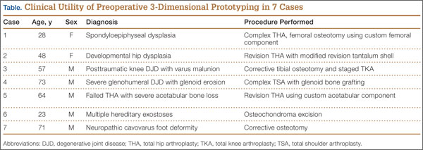
Case Reports
Case 1
A 28-year-old woman with a history of spondyloepiphyseal dysplasia presented to our clinic with bilateral hip pain. About 8 years earlier, she had undergone bilateral proximal and distal femoral osteotomies. Her function had initially improved, but over the 2 to 3 years before presentation she began having more pain and stiffness with activity. At time of initial evaluation, she was able to walk only 1 to 2 blocks and had difficulty getting in and out of a car and up out of a seated position.
On physical examination, the patient was 3 feet 10 inches tall and weighed 77 pounds. She ambulated with decreased stance phase on both lower extremities and had developed a significant amount of increased forward pelvic inclination and increased lumbar lordosis. Both hips and thighs had multiple healed scars from prior surgeries and pin tracts. Range of motion (ROM) on both sides was restricted to 85° of flexion, 10° of internal rotation, 15° of external rotation, and 15° of abduction.
Plain radiographs showed advanced degenerative joint disease (DJD) of both hips with dysplastic acetabuli and evidence of healed osteotomies (Figure 1). Femoral deformities, noted bilaterally, consisted of marked valgus proximally and varus distally. Preoperative CT was used to create a 3-D model of the pelvis and femur. The model was created by the same implant manufacturer that produced the final components (Depuy, Warsaw, Indiana). Corrective femoral osteotomy was performed on the model to allow for design and use of a custom implant, while the modeled pelvis confirmed the ability to reproduce the normal hip center with a 44-mm conventional hemispherical socket.
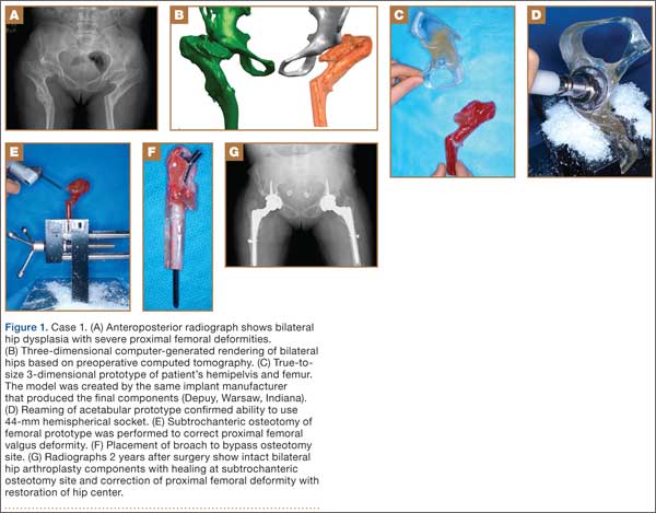
After surgery, the patient was able to ambulate without a limp and return to work. Her hip ROM was pain-free passively and actively with flexion to 100°, internal rotation to 35°, external rotation to 20°, and abduction to 30°.
Case 2
A 48-year-old woman with a history of Crowe IV hip dysplasia presented to our clinic with a chronically dislocated right total hip arthroplasty (THA) (Figure 2). Her initial THA was revised 1 year later because of acetabular component failure. Two years later, she was diagnosed with a deep periprosthetic infection, which was ultimately treated with 2-stage reimplantation. She subsequently dislocated and underwent re-revision of the S-ROM body and stem (DePuy Synthes, Warsaw, Indiana). At a visit after that revision, she was noted to be chronically dislocated, and was sent to our clinic for further management.
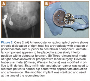
Preoperative radiographs showed a right uncemented THA with the femoral head dislocated toward the false acetabulum, retained hardware, and an old ununited trochanteric fragment. Both the femoral and acetabular components appeared well-fixed, though the acetabular component was positioned inferior, toward the obturator foramen.
Preoperative CT with metal artifact subtraction was used to create a 3-D model of the residual bony pelvis. The model was made by an implant manufacturer (Zimmer, Warsaw, Indiana). The shape of the superior defect was amenable to reconstruction using a modified revision trabecular metal socket. The pelvic model was reamed to accept a conventional hemispherical socket. The defect was reamed to accept a modified revision trabecular metal socket. The real implant was fashioned before surgery and was sterilized to avoid the need for intraoperative modification. Use of the preoperative model significantly reduced the time that would have been needed to modify the implant during actual surgery.
The patient’s right THA was revised. At time of surgery, the modified revision trabecular metal acetabular component was noted to seat appropriately in the superior defect. The true acetabulum was reestablished, and a hemispherical socket was placed with multiple screws. The 2 components were then unitized using cement in the same manner as would be done with an off-the-shelf augment.
Case 3
A 57-year-old man presented with a 10-year history of right knee pain. About 30 years before presentation at our clinic, he was treated for an open right tibia fracture sustained in a motorcycle accident. He had been treated nonsurgically, with injections, but they failed to provide sustained relief.
Preoperative radiographs showed severe advanced DJD in conjunction with an extra-articular posttraumatic varus tibial shaft deformity (Figure 3). An implant manufacturer (Zimmer) used a CT scan to create a model of the deformity. The resultant center of rotation angle was calculated using preoperative images and conventional techniques for deformity correction, and a lateral closing-wedge osteotomy was performed on the CT-based model. The initial attempt at deformity correction was slightly excessive, and the amount of resected bone slightly thicker than the calculated wedge, resulting in a valgus deformity. This error was noted, and the decision was made to recut a new model with a slight amount of residual varus that could be corrected during the final knee arthroplasty procedure.
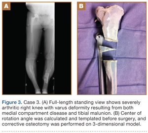
Corrective osteotomy was performed with a lateral plate. Six months later, the patient had no residual pain, and CT confirmed union at the osteotomy site and a slight amount of residual varus. The patient then underwent routine total knee arthroplasty (TKA) using an abbreviated keel to avoid the need for removal of the previously placed hardware. The varus deformity was completely corrected.
Case 4
A 73-year-old man had a history of shoulder pain dating back to his childhood. Despite treatment with nonsteroidal anti-inflammatory drugs, physical therapy, and injections, his debilitating pain persisted. Physical examination revealed limited ROM and an intact rotator cuff.
Plain radiographs showed severe DJD of the glenohumeral joint (Figure 4). Severe erosions of the glenoid were noted, prompting further workup with CT, which showed significant bone loss, particularly along the posterior margin of the glenoid. We used our 3-D printer to create a model of the scapula from CT images. The model was then reamed in the usual fashion to accept a 3-pegged glenoid component. On placement of a trial implant, a large deficiency was seen posteriorly. We thought the size and location of the defect made it amenable to grafting using the patient’s humeral head.
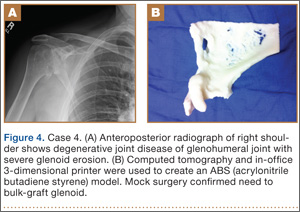
The patient elected to undergo right total shoulder arthroplasty. During the procedure, the glenoid defect was found to be identical to what was encountered with the model before surgery. A portion of the patient’s humeral head was then fashioned to fit the defect, and was secured with three 2.7-mm screws, after provisional fixation using 2.0-mm Kirschner wires. The screws were countersunk, and the graft was contoured by hand to match the previous reaming. A 3-pegged 52-mm glenoid component was then cemented into position with excellent stability.
Case 5
A 64-year-old man presented to our clinic with left hip pain 40 years after THA. The original procedure was performed for resolved proximal femoral osteomyelitis. Plain radiographs showed a loose cemented McKee-Farrar hip arthroplasty (Figure 5). Because of the elevated position of the acetabular component relative to the native hip center, CT was used to determine the amount of femoral bone loss.
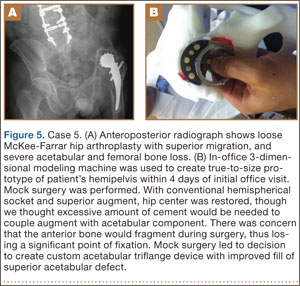
We used our 3-D printer to create a model and tried to recreate the native hip center with conventional off-the-shelf implants. A 50-mm hemispherical socket trial was placed in the appropriate location, along with a trabecular metal augment trial to provide extended coverage over the superolateral portion of the socket. Noted between the socket and the augment was a large gap; a substantial amount of cement would have been needed to unitize the construct. We thought a custom acetabular component would avoid the need for cement. In addition, given the patient’s small stature, the conventional acetabular component would allow a head only 32 mm in diameter. With a custom implant, the head could be enlarged to 36 mm, providing improved ROM and stability.
The patient underwent revision left hip arthroplasty using a custom acetabular component. A 3-D model available at time of surgery was used to aid implant placement.
Case 6
A 23-year-old man with multiple hereditary exostoses presented to our clinic with a painful mass in the left calf. Plain radiographs showed extensive osteochondromatosis involving the left proximal tibiofibular joint (Figure 6). The exostosis extended posteromedially, displacing the arterial trifurcation. MRI showed a small cartilage cap without evidence of malignant transformation.
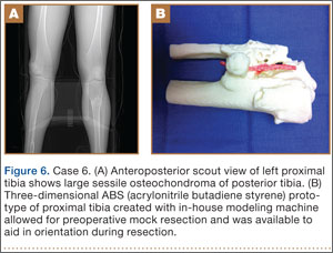
CT angiogram allowed the vasculature to be modeled along with the deformity. A 3-D model was fabricated. The model included the entire proximal tibiofibular joint, as well as the anterior tibial, peroneal, and posterior tibial arteries. Cautious intralesional resection was recommended because of the proximity to all 3 vessels.
The patient underwent tumor resection through a longitudinal posterior approach. The interval between the medial and lateral heads of the gastrocnemius muscles was developed to expose the underlying soleus muscle. The soleus was split longitudinally from its hiatus to the inferior portion of the exostosis. This allowed for identification of the trifurcation and the tibial nerve, which were protected. Osteotomes were used to resect the mass at its base, the edges were carefully trimmed, and bone wax was placed over the defect. Anterior and lateral to this mass was another large mass (under the soleus muscle), which was also transected using an osteotome. The gastrocnemius and soleus muscles were then reflected off the fibula in order to remove 2 other exostoses, beneath the neck and head of the fibula.
Case 7
A 71-year-old man with a history of idiopathic lymphedema and peripheral neuropathy presented to our clinic with a left cavovarus foot deformity and a history of recurrent neuropathic foot ulcers (Figure 7). Physical examination revealed a callus over the lateral aspect of the base of the fifth metatarsal. Preoperative radiograph showed evidence of prior triple arthrodesis with a cavovarus foot deformity. CT scan was used to create a 3-D model of the foot. The model was then used to identify an appropriate location for lateral midtarsal and calcaneal closing-wedge osteotomies.
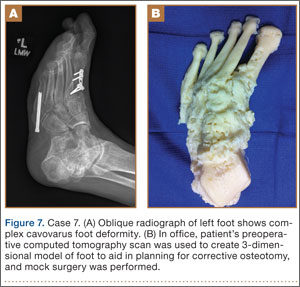
The patient underwent midfoot and hindfoot surgical correction. At surgery, the lateral closing-wedge osteotomies were performed according to the preoperative model. Radiographs 1 year after surgery showed correction of the forefoot varus.
Discussion
Three-dimensional printing for medical applications of anatomical modeling is not a new concept.1,3,4 Its use has been reported for a variety of applications in orthopedic surgery, including the printing of porous and metallic surfaces5 and bone-tissue engineering.6-9 Rapid prototyping for medical application was first reported in 1990 when a CT-based model was used to create a cranial bone.10 Reports of using the technique are becoming more widespread, particularly in the dental and maxillofacial literature, which includes reports on a variety of applications, including patient-specific drill guides, splints, and implants.11-14 The ability to perform mock surgery in advance of an actual procedure provides an invaluable opportunity to anticipate potential intraoperative problems, reduce operative time, and improve the accuracy of reconstruction.
Office-based rapid prototyping that uses an in-house 3-D printer is a novel application of this technology. It allows for creation of a patient-specific model for preoperative planning purposes. We are unaware of any other reports demonstrating the breadth and utility of office-based rapid prototyping in orthopedic surgery. For general reference, a printer similar to ours requires an initial investment of $52,000 to $56,000. This cost generally covers the printer, printer base cabinet, installation, training, and printer software (different from the 3-D modeling software), plus a 1-year warranty. A service agreement costs about $4000 annually. Printer and model supply expenses depend on the material used for the model (eg, ABS [acrylonitrile butadiene styrene]) and on the size and complexity of the 3-D models created. Average time to generate an appropriately formatted 3-D printing file is about 1 hour, though times can vary largely, according to amount of metal artifact subtraction necessary and the experience of the software user. For the rare, extremely complex deformities that require a significant amount of metal artifact subtraction, file preparation times can exceed 3 or 4 hours. We think these preparation times will decrease as communication between radiology file export format and modeling software ultimately allows for metal artifact subtraction images to function within the modeling software environment. Once an appropriately formatted file has been created, typical printing times vary according to the size of the to-be-modeled bone. For a hemipelvis, printing time is 30 to 40 hours; printing that is started on a Friday afternoon will be complete by Monday morning.
There are few reports of rapid prototyping in orthopedic surgery. In 2003, Minns and colleagues15 used a 3-D model in the planning of a tibial resection for TKA. They found the model to be accurate at time of surgery, resulting in appropriate tibial coverage by a conventional meniscal-bearing implant. Munjal and colleagues16 reported on 10 complex failed hip arthroplasty cases in which patients had revision surgery after preoperative planning using 3-D modeling techniques. The authors found that, in 8 of the 10 cases, conventional classification systems of bone loss were inaccurate in comparison with the prototype. Four cases required reconstruction with a custom triflange when conventional implants were not deemed reasonable based on the pelvic model. Tam and colleagues17 reported using a 3-D prototype as an aid in surgical planning for resection of a scapular osteochondroma in a 6-year-old patient. They found the rapid prototype to be useful at time of resection—similar to what we found with 1 patient (case 6). Adding contrast media to our patient’s scan allowed for 3-D visualization of the lesion and the encased vasculature. Fu and colleagues18 reported using a patient-specific drill template to insert anterior transpedicular screws. They constructed 24 prototypes of a formalin-preserved cervical vertebra to create a patient-specific biocompatible drill template for use in correcting multilevel cervical instability. They found the technique to be highly reproducible and accurate. Zein and colleagues19 used a rapid prototype of 3 consecutive human livers to preoperatively identify the vascular and biliary tract anatomy. They reported a high degree of accuracy—mean dimensional errors of less than 4 mm for the entire model and 1.3 mm for the vascular diameter.
The models created by implant manufacturers in this series were used to perform “mock” surgery before the actual procedures. Working with these models prompted us to buy our own 3-D printer. The learning curve can be steep, but commercially available 3-D printers allow for prompt in-office production of high-quality realistic prototypes at relatively low per-case cost (Figure 8). Three-dimensional modeling allows surgeons to assess the accuracy of their original surgical plans and, if necessary, correct them before surgery. Although computer-aided design models are useful, the ability to “perform surgery preoperatively” adds another element to surgeons’ understanding of the potential issues that may arise. Also, an in-office printer can help improve surgeons’ understanding and control over the process by which images are translated from radiographic file to 3-D model. Disadvantages of an in-office system include start-up and maintenance costs, office space requirements, and a significant learning curve for software and hardware applications. In addition, creation of 3-D models requires close interaction with radiologists who can provide appropriately formatted DICOM images, as metal artifact subtraction can be challenging. We think that, as image formatting and software capabilities are continually refined, this technology will become an invaluable part of multiple subspecialties across orthopedic surgery, with potentially infinite clinical, educational, and research applications.
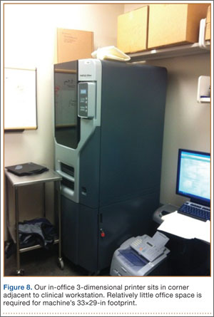
1. McGurk M, Amis AA, Potamianos P, Goodger NM. Rapid prototyping techniques for anatomical modelling in medicine. Ann R Coll Surg Engl. 1997;79(3):169-174.
2. Webb PA. A review of rapid prototyping (RP) techniques in the medical and biomedical sector. J Med Eng Technol. 2000;24(4):149-153.
3. Esses SJ, Berman P, Bloom AI, Sosna J. Clinical applications of physical 3D models derived from MDCT data and created by rapid prototyping. AJR Am J Roentgenol. 2011;196(6):W683-W688.
4. Torres K, Staśkiewicz G, Śnieżyński M, Drop A, Maciejewski R. Application of rapid prototyping techniques for modelling of anatomical structures in medical training and education. Folia Morphol. 2011;70(1):1-4.
5. Melican MC, Zimmerman MC, Dhillon MS, Ponnambalam AR, Curodeau A, Parsons JR. Three-dimensional printing and porous metallic surfaces: a new orthopedic application. J Biomed Mater Res. 2001;55(2):194-202.
6. Butscher A, Bohner M, Hofmann S, Gauckler L, Müller R. Structural and material approaches to bone tissue engineering in powder-based three-dimensional printing. Acta Biomater. 2011;7(3):907-920.
7. Ciocca L, De Crescenzio F, Fantini M, Scotti R. CAD/CAM and rapid prototyped scaffold construction for bone regenerative medicine and surgical transfer of virtual planning: a pilot study. Comput Med Imaging Graph. 2009;33(1):58-62.
8. Leukers B, Gülkan H, Irsen SH, et al. Hydroxyapatite scaffolds for bone tissue engineering made by 3D printing. J Mater Sci Mater Med. 2005;16(12):1121-1124.
9. Seitz H, Rieder W, Irsen S, Leukers B, Tille C. Three-dimensional printing of porous ceramic scaffolds for bone tissue engineering. J Biomed Mater Res B Appl Biomater. 2005;74(2):782-788.
10. Mankovich NJ, Cheeseman AM, Stoker NG. The display of three-dimensional anatomy with stereolithographic models. J Digit Imaging. 1990;3(3):200-203.
11. Flügge TV, Nelson K, Schmelzeisen R, Metzger MC. Three-dimensional plotting and printing of an implant drilling guide: simplifying guided implant surgery. J Oral Maxillofac Surg. 2013;71(8):1340-1346.
12. Goiato MC, Santos MR, Pesqueira AA, Moreno A, dos Santos DM, Haddad MF. Prototyping for surgical and prosthetic treatment. J Craniofac Surg. 2011;22(3):914-917.
13. Metzger MC, Hohlweg-Majert B, Schwarz U, Teschner M, Hammer B, Schmelzeisen R. Manufacturing splints for orthognathic surgery using a three-dimensional printer. Oral Surg Oral Med Oral Pathol Oral Radiol Endod. 2008;105(2):e1-e7.
14. Robiony M, Salvo I, Costa F, et al. Virtual reality surgical planning for maxillofacial distraction osteogenesis: the role of reverse engineering rapid prototyping and cooperative work. J Oral Maxillofac Surg. 2007;65(6):1198-1208.
15. Minns RJ, Bibb R, Banks R, Sutton RA. The use of a reconstructed three-dimensional solid model from CT to aid the surgical management of a total knee arthroplasty: a case study. Med Eng Phys. 2003;25(6):523-526.
16. Munjal S, Leopold SS, Kornreich D, Shott S, Finn HA. CT-generated 3-dimensional models for complex acetabular reconstruction. J Arthroplasty. 2000;15(5):644-653.
17. Tam MD, Laycock SD, Bell D, Chojnowski A. 3-D printout of a DICOM file to aid surgical planning in a 6 year old patient with a large scapular osteochondroma complicating congenital diaphyseal aclasia. J Radiol Case Rep. 2012;6(1):31-37.
18. Fu M, Lin L, Kong X, et al. Construction and accuracy assessment of patient-specific biocompatible drill template for cervical anterior transpedicular screw (ATPS) insertion: an in vitro study. PLoS One. 2013;8(1):e53580.
19. Zein NN, Hanouneh IA, Bishop PD, et al. Three-dimensional print of a liver for preoperative planning in living donor liver transplantation. Liver Transpl. 2013;19(12):1304-1310.
Three-dimensional (3-D) printing is a rapidly evolving technology with both medical and nonmedical applications.1,2 Rapid prototyping involves creating a physical model of human tissue from a 3-D computer-generated rendering.3 The method relies on export of Digital Imaging and Communications in Medicine (DICOM)–based computed tomography (CT) or magnetic resonance imaging (MRI) data into standard triangular language (STL) format. Reducing CT or MRI slice thickness increases resolution of the final model.2 Five types of rapid prototyping exist: STL, selective laser sintering, fused deposition modeling, multijet modeling, and 3-D printing.
Most implant manufacturers can produce a 3-D model based on surgeon-provided DICOM images. The ability to produce anatomical models in an office-based setting is a more recent development. Three-dimensional modeling may allow for more accurate and extensive preoperative planning than radiographic examination alone does, and may even allow surgeons to perform procedures as part of preoperative preparation. This can allow for early recognition of unanticipated intraoperative problems or of the need for special techniques and implants that would not have been otherwise available, all of which may ultimately reduce operative time.
The breadth of applications for office-based 3-D prototyping is not well described in the orthopedic surgery literature. In this article, we describe 7 cases of complex orthopedic disorders that were surgically treated after preoperative planning in which use of a 3-D printer allowed for “mock” surgery before the actual procedures. In 3 of the cases, the models were made by the implant manufacturers. Working with these models prompted us to buy a 3-D printer (Fortus 250; Stratasys, Eden Prairie, Minnesota) for in-office use. In the other 4 cases, we used this printer to create our own models. As indicated in the manufacturer’s literature, the printer uses fused deposition modeling, which builds a model layer by layer by heating thermoplastic material to a semi-liquid state and extruding it according to computer-controlled pathways.
We present preoperative images, preoperative 3-D modeling, and intraoperative and postoperative images along with brief case descriptions (Table). The patients provided written informed consent for print and electronic publication of these case reports.
Case Reports
Case 1
A 28-year-old woman with a history of spondyloepiphyseal dysplasia presented to our clinic with bilateral hip pain. About 8 years earlier, she had undergone bilateral proximal and distal femoral osteotomies. Her function had initially improved, but over the 2 to 3 years before presentation she began having more pain and stiffness with activity. At time of initial evaluation, she was able to walk only 1 to 2 blocks and had difficulty getting in and out of a car and up out of a seated position.
On physical examination, the patient was 3 feet 10 inches tall and weighed 77 pounds. She ambulated with decreased stance phase on both lower extremities and had developed a significant amount of increased forward pelvic inclination and increased lumbar lordosis. Both hips and thighs had multiple healed scars from prior surgeries and pin tracts. Range of motion (ROM) on both sides was restricted to 85° of flexion, 10° of internal rotation, 15° of external rotation, and 15° of abduction.
Plain radiographs showed advanced degenerative joint disease (DJD) of both hips with dysplastic acetabuli and evidence of healed osteotomies (Figure 1). Femoral deformities, noted bilaterally, consisted of marked valgus proximally and varus distally. Preoperative CT was used to create a 3-D model of the pelvis and femur. The model was created by the same implant manufacturer that produced the final components (Depuy, Warsaw, Indiana). Corrective femoral osteotomy was performed on the model to allow for design and use of a custom implant, while the modeled pelvis confirmed the ability to reproduce the normal hip center with a 44-mm conventional hemispherical socket.
After surgery, the patient was able to ambulate without a limp and return to work. Her hip ROM was pain-free passively and actively with flexion to 100°, internal rotation to 35°, external rotation to 20°, and abduction to 30°.
Case 2
A 48-year-old woman with a history of Crowe IV hip dysplasia presented to our clinic with a chronically dislocated right total hip arthroplasty (THA) (Figure 2). Her initial THA was revised 1 year later because of acetabular component failure. Two years later, she was diagnosed with a deep periprosthetic infection, which was ultimately treated with 2-stage reimplantation. She subsequently dislocated and underwent re-revision of the S-ROM body and stem (DePuy Synthes, Warsaw, Indiana). At a visit after that revision, she was noted to be chronically dislocated, and was sent to our clinic for further management.
Preoperative radiographs showed a right uncemented THA with the femoral head dislocated toward the false acetabulum, retained hardware, and an old ununited trochanteric fragment. Both the femoral and acetabular components appeared well-fixed, though the acetabular component was positioned inferior, toward the obturator foramen.
Preoperative CT with metal artifact subtraction was used to create a 3-D model of the residual bony pelvis. The model was made by an implant manufacturer (Zimmer, Warsaw, Indiana). The shape of the superior defect was amenable to reconstruction using a modified revision trabecular metal socket. The pelvic model was reamed to accept a conventional hemispherical socket. The defect was reamed to accept a modified revision trabecular metal socket. The real implant was fashioned before surgery and was sterilized to avoid the need for intraoperative modification. Use of the preoperative model significantly reduced the time that would have been needed to modify the implant during actual surgery.
The patient’s right THA was revised. At time of surgery, the modified revision trabecular metal acetabular component was noted to seat appropriately in the superior defect. The true acetabulum was reestablished, and a hemispherical socket was placed with multiple screws. The 2 components were then unitized using cement in the same manner as would be done with an off-the-shelf augment.
Case 3
A 57-year-old man presented with a 10-year history of right knee pain. About 30 years before presentation at our clinic, he was treated for an open right tibia fracture sustained in a motorcycle accident. He had been treated nonsurgically, with injections, but they failed to provide sustained relief.
Preoperative radiographs showed severe advanced DJD in conjunction with an extra-articular posttraumatic varus tibial shaft deformity (Figure 3). An implant manufacturer (Zimmer) used a CT scan to create a model of the deformity. The resultant center of rotation angle was calculated using preoperative images and conventional techniques for deformity correction, and a lateral closing-wedge osteotomy was performed on the CT-based model. The initial attempt at deformity correction was slightly excessive, and the amount of resected bone slightly thicker than the calculated wedge, resulting in a valgus deformity. This error was noted, and the decision was made to recut a new model with a slight amount of residual varus that could be corrected during the final knee arthroplasty procedure.
Corrective osteotomy was performed with a lateral plate. Six months later, the patient had no residual pain, and CT confirmed union at the osteotomy site and a slight amount of residual varus. The patient then underwent routine total knee arthroplasty (TKA) using an abbreviated keel to avoid the need for removal of the previously placed hardware. The varus deformity was completely corrected.
Case 4
A 73-year-old man had a history of shoulder pain dating back to his childhood. Despite treatment with nonsteroidal anti-inflammatory drugs, physical therapy, and injections, his debilitating pain persisted. Physical examination revealed limited ROM and an intact rotator cuff.
Plain radiographs showed severe DJD of the glenohumeral joint (Figure 4). Severe erosions of the glenoid were noted, prompting further workup with CT, which showed significant bone loss, particularly along the posterior margin of the glenoid. We used our 3-D printer to create a model of the scapula from CT images. The model was then reamed in the usual fashion to accept a 3-pegged glenoid component. On placement of a trial implant, a large deficiency was seen posteriorly. We thought the size and location of the defect made it amenable to grafting using the patient’s humeral head.
The patient elected to undergo right total shoulder arthroplasty. During the procedure, the glenoid defect was found to be identical to what was encountered with the model before surgery. A portion of the patient’s humeral head was then fashioned to fit the defect, and was secured with three 2.7-mm screws, after provisional fixation using 2.0-mm Kirschner wires. The screws were countersunk, and the graft was contoured by hand to match the previous reaming. A 3-pegged 52-mm glenoid component was then cemented into position with excellent stability.
Case 5
A 64-year-old man presented to our clinic with left hip pain 40 years after THA. The original procedure was performed for resolved proximal femoral osteomyelitis. Plain radiographs showed a loose cemented McKee-Farrar hip arthroplasty (Figure 5). Because of the elevated position of the acetabular component relative to the native hip center, CT was used to determine the amount of femoral bone loss.
We used our 3-D printer to create a model and tried to recreate the native hip center with conventional off-the-shelf implants. A 50-mm hemispherical socket trial was placed in the appropriate location, along with a trabecular metal augment trial to provide extended coverage over the superolateral portion of the socket. Noted between the socket and the augment was a large gap; a substantial amount of cement would have been needed to unitize the construct. We thought a custom acetabular component would avoid the need for cement. In addition, given the patient’s small stature, the conventional acetabular component would allow a head only 32 mm in diameter. With a custom implant, the head could be enlarged to 36 mm, providing improved ROM and stability.
The patient underwent revision left hip arthroplasty using a custom acetabular component. A 3-D model available at time of surgery was used to aid implant placement.
Case 6
A 23-year-old man with multiple hereditary exostoses presented to our clinic with a painful mass in the left calf. Plain radiographs showed extensive osteochondromatosis involving the left proximal tibiofibular joint (Figure 6). The exostosis extended posteromedially, displacing the arterial trifurcation. MRI showed a small cartilage cap without evidence of malignant transformation.
CT angiogram allowed the vasculature to be modeled along with the deformity. A 3-D model was fabricated. The model included the entire proximal tibiofibular joint, as well as the anterior tibial, peroneal, and posterior tibial arteries. Cautious intralesional resection was recommended because of the proximity to all 3 vessels.
The patient underwent tumor resection through a longitudinal posterior approach. The interval between the medial and lateral heads of the gastrocnemius muscles was developed to expose the underlying soleus muscle. The soleus was split longitudinally from its hiatus to the inferior portion of the exostosis. This allowed for identification of the trifurcation and the tibial nerve, which were protected. Osteotomes were used to resect the mass at its base, the edges were carefully trimmed, and bone wax was placed over the defect. Anterior and lateral to this mass was another large mass (under the soleus muscle), which was also transected using an osteotome. The gastrocnemius and soleus muscles were then reflected off the fibula in order to remove 2 other exostoses, beneath the neck and head of the fibula.
Case 7
A 71-year-old man with a history of idiopathic lymphedema and peripheral neuropathy presented to our clinic with a left cavovarus foot deformity and a history of recurrent neuropathic foot ulcers (Figure 7). Physical examination revealed a callus over the lateral aspect of the base of the fifth metatarsal. Preoperative radiograph showed evidence of prior triple arthrodesis with a cavovarus foot deformity. CT scan was used to create a 3-D model of the foot. The model was then used to identify an appropriate location for lateral midtarsal and calcaneal closing-wedge osteotomies.
The patient underwent midfoot and hindfoot surgical correction. At surgery, the lateral closing-wedge osteotomies were performed according to the preoperative model. Radiographs 1 year after surgery showed correction of the forefoot varus.
Discussion
Three-dimensional printing for medical applications of anatomical modeling is not a new concept.1,3,4 Its use has been reported for a variety of applications in orthopedic surgery, including the printing of porous and metallic surfaces5 and bone-tissue engineering.6-9 Rapid prototyping for medical application was first reported in 1990 when a CT-based model was used to create a cranial bone.10 Reports of using the technique are becoming more widespread, particularly in the dental and maxillofacial literature, which includes reports on a variety of applications, including patient-specific drill guides, splints, and implants.11-14 The ability to perform mock surgery in advance of an actual procedure provides an invaluable opportunity to anticipate potential intraoperative problems, reduce operative time, and improve the accuracy of reconstruction.
Office-based rapid prototyping that uses an in-house 3-D printer is a novel application of this technology. It allows for creation of a patient-specific model for preoperative planning purposes. We are unaware of any other reports demonstrating the breadth and utility of office-based rapid prototyping in orthopedic surgery. For general reference, a printer similar to ours requires an initial investment of $52,000 to $56,000. This cost generally covers the printer, printer base cabinet, installation, training, and printer software (different from the 3-D modeling software), plus a 1-year warranty. A service agreement costs about $4000 annually. Printer and model supply expenses depend on the material used for the model (eg, ABS [acrylonitrile butadiene styrene]) and on the size and complexity of the 3-D models created. Average time to generate an appropriately formatted 3-D printing file is about 1 hour, though times can vary largely, according to amount of metal artifact subtraction necessary and the experience of the software user. For the rare, extremely complex deformities that require a significant amount of metal artifact subtraction, file preparation times can exceed 3 or 4 hours. We think these preparation times will decrease as communication between radiology file export format and modeling software ultimately allows for metal artifact subtraction images to function within the modeling software environment. Once an appropriately formatted file has been created, typical printing times vary according to the size of the to-be-modeled bone. For a hemipelvis, printing time is 30 to 40 hours; printing that is started on a Friday afternoon will be complete by Monday morning.
There are few reports of rapid prototyping in orthopedic surgery. In 2003, Minns and colleagues15 used a 3-D model in the planning of a tibial resection for TKA. They found the model to be accurate at time of surgery, resulting in appropriate tibial coverage by a conventional meniscal-bearing implant. Munjal and colleagues16 reported on 10 complex failed hip arthroplasty cases in which patients had revision surgery after preoperative planning using 3-D modeling techniques. The authors found that, in 8 of the 10 cases, conventional classification systems of bone loss were inaccurate in comparison with the prototype. Four cases required reconstruction with a custom triflange when conventional implants were not deemed reasonable based on the pelvic model. Tam and colleagues17 reported using a 3-D prototype as an aid in surgical planning for resection of a scapular osteochondroma in a 6-year-old patient. They found the rapid prototype to be useful at time of resection—similar to what we found with 1 patient (case 6). Adding contrast media to our patient’s scan allowed for 3-D visualization of the lesion and the encased vasculature. Fu and colleagues18 reported using a patient-specific drill template to insert anterior transpedicular screws. They constructed 24 prototypes of a formalin-preserved cervical vertebra to create a patient-specific biocompatible drill template for use in correcting multilevel cervical instability. They found the technique to be highly reproducible and accurate. Zein and colleagues19 used a rapid prototype of 3 consecutive human livers to preoperatively identify the vascular and biliary tract anatomy. They reported a high degree of accuracy—mean dimensional errors of less than 4 mm for the entire model and 1.3 mm for the vascular diameter.
The models created by implant manufacturers in this series were used to perform “mock” surgery before the actual procedures. Working with these models prompted us to buy our own 3-D printer. The learning curve can be steep, but commercially available 3-D printers allow for prompt in-office production of high-quality realistic prototypes at relatively low per-case cost (Figure 8). Three-dimensional modeling allows surgeons to assess the accuracy of their original surgical plans and, if necessary, correct them before surgery. Although computer-aided design models are useful, the ability to “perform surgery preoperatively” adds another element to surgeons’ understanding of the potential issues that may arise. Also, an in-office printer can help improve surgeons’ understanding and control over the process by which images are translated from radiographic file to 3-D model. Disadvantages of an in-office system include start-up and maintenance costs, office space requirements, and a significant learning curve for software and hardware applications. In addition, creation of 3-D models requires close interaction with radiologists who can provide appropriately formatted DICOM images, as metal artifact subtraction can be challenging. We think that, as image formatting and software capabilities are continually refined, this technology will become an invaluable part of multiple subspecialties across orthopedic surgery, with potentially infinite clinical, educational, and research applications.
1. McGurk M, Amis AA, Potamianos P, Goodger NM. Rapid prototyping techniques for anatomical modelling in medicine. Ann R Coll Surg Engl. 1997;79(3):169-174.
2. Webb PA. A review of rapid prototyping (RP) techniques in the medical and biomedical sector. J Med Eng Technol. 2000;24(4):149-153.
3. Esses SJ, Berman P, Bloom AI, Sosna J. Clinical applications of physical 3D models derived from MDCT data and created by rapid prototyping. AJR Am J Roentgenol. 2011;196(6):W683-W688.
4. Torres K, Staśkiewicz G, Śnieżyński M, Drop A, Maciejewski R. Application of rapid prototyping techniques for modelling of anatomical structures in medical training and education. Folia Morphol. 2011;70(1):1-4.
5. Melican MC, Zimmerman MC, Dhillon MS, Ponnambalam AR, Curodeau A, Parsons JR. Three-dimensional printing and porous metallic surfaces: a new orthopedic application. J Biomed Mater Res. 2001;55(2):194-202.
6. Butscher A, Bohner M, Hofmann S, Gauckler L, Müller R. Structural and material approaches to bone tissue engineering in powder-based three-dimensional printing. Acta Biomater. 2011;7(3):907-920.
7. Ciocca L, De Crescenzio F, Fantini M, Scotti R. CAD/CAM and rapid prototyped scaffold construction for bone regenerative medicine and surgical transfer of virtual planning: a pilot study. Comput Med Imaging Graph. 2009;33(1):58-62.
8. Leukers B, Gülkan H, Irsen SH, et al. Hydroxyapatite scaffolds for bone tissue engineering made by 3D printing. J Mater Sci Mater Med. 2005;16(12):1121-1124.
9. Seitz H, Rieder W, Irsen S, Leukers B, Tille C. Three-dimensional printing of porous ceramic scaffolds for bone tissue engineering. J Biomed Mater Res B Appl Biomater. 2005;74(2):782-788.
10. Mankovich NJ, Cheeseman AM, Stoker NG. The display of three-dimensional anatomy with stereolithographic models. J Digit Imaging. 1990;3(3):200-203.
11. Flügge TV, Nelson K, Schmelzeisen R, Metzger MC. Three-dimensional plotting and printing of an implant drilling guide: simplifying guided implant surgery. J Oral Maxillofac Surg. 2013;71(8):1340-1346.
12. Goiato MC, Santos MR, Pesqueira AA, Moreno A, dos Santos DM, Haddad MF. Prototyping for surgical and prosthetic treatment. J Craniofac Surg. 2011;22(3):914-917.
13. Metzger MC, Hohlweg-Majert B, Schwarz U, Teschner M, Hammer B, Schmelzeisen R. Manufacturing splints for orthognathic surgery using a three-dimensional printer. Oral Surg Oral Med Oral Pathol Oral Radiol Endod. 2008;105(2):e1-e7.
14. Robiony M, Salvo I, Costa F, et al. Virtual reality surgical planning for maxillofacial distraction osteogenesis: the role of reverse engineering rapid prototyping and cooperative work. J Oral Maxillofac Surg. 2007;65(6):1198-1208.
15. Minns RJ, Bibb R, Banks R, Sutton RA. The use of a reconstructed three-dimensional solid model from CT to aid the surgical management of a total knee arthroplasty: a case study. Med Eng Phys. 2003;25(6):523-526.
16. Munjal S, Leopold SS, Kornreich D, Shott S, Finn HA. CT-generated 3-dimensional models for complex acetabular reconstruction. J Arthroplasty. 2000;15(5):644-653.
17. Tam MD, Laycock SD, Bell D, Chojnowski A. 3-D printout of a DICOM file to aid surgical planning in a 6 year old patient with a large scapular osteochondroma complicating congenital diaphyseal aclasia. J Radiol Case Rep. 2012;6(1):31-37.
18. Fu M, Lin L, Kong X, et al. Construction and accuracy assessment of patient-specific biocompatible drill template for cervical anterior transpedicular screw (ATPS) insertion: an in vitro study. PLoS One. 2013;8(1):e53580.
19. Zein NN, Hanouneh IA, Bishop PD, et al. Three-dimensional print of a liver for preoperative planning in living donor liver transplantation. Liver Transpl. 2013;19(12):1304-1310.
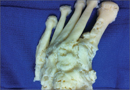
Well-Leg Positioning on a Fracture Table: Using a Pillow Sling
The development of acute compartment syndrome in lower legs placed in the lithotomy position is a rare complication reported within various surgical subspecialties, including general surgery, gynecology, and urology.1-5 Although it is reported in arthroscopic knee cases, the more frequent occurrence in orthopedics, based on available case reports, appears to involve the well (uninjured or contralateral) leg placed in the hemilithotomy position on the fracture table.6-9
Prior studies have found significantly elevated lower leg compartment pressures in legs placed in the lithotomy position. Chase and colleagues10 measured the anterior compartment pressures in 16 limbs placed in the lithotomy position. They found minor elevations after initial lithotomy positioning, but gradual increases over time, with an average elevation to 30 mm Hg and maximum of 70 mm Hg. Similarly, Meyer and colleagues11 recorded the lower leg pressures in 8 healthy volunteers positioned on a fracture table. Changing from the supine position to the lithotomy position significantly increased the intramuscular pressure in the anterior compartment (from 11.6 to 19.4 mm Hg) and in the lateral compartment (from 13.0 to 25.8 mm Hg).
Along with increased intramuscular pressures, local hypotension occurs in lower legs placed in the lithotomy position. Mean diastolic blood pressure in the ankle was 63.9 mm Hg in the leg placed in the supine position as opposed to 34.6 mm Hg in the same leg placed in the lithotomy position.10 This finding is not unexpected, given that local arteriolar pressure decreases by 0.78 mm Hg for every 1.0 cm of elevation.12-14 Furthermore, some “kinking” of either femoral vessels at the hip or popliteal vessels at the knee may also occur.15
For prevention of these problems, the well leg can be placed in a position of slight hip extension and full knee extension on the fracture table—the so-called scissored position. This position is commonly achieved with an additional traction boot and support bar connected to the well leg. However, this additional setup can make positioning the C-arm machine difficult; there is obstruction by the additional support bars and the leg itself. In addition, the uninjured extremity may be placed into positions that cause unnecessarily high stresses across the joints and can potentially lead to iatrogenic injury and pain.
Risk of fracture in the well leg results from the C-arm machine abutting the well leg when swinging through to obtain a lateral image. This problem is overcome by securing the well leg to the fracture table’s longitudinal support bar using a pillow sling, thereby reducing the risks of compartment syndrome, allowing the uninjured limb to be in a relaxed position, and allowing good fluoroscopic images to easily be obtained. This brief report is an introduction to this positioning method.
Surgical Technique
The patient is intubated and anesthetized on the hospital bed before being transferred to the fracture table. On the fracture table, the operative leg is placed in a boot traction device in the standard fashion. The perineal post is then inserted, and the patient is pulled caudally on the bed so that the post is appropriately positioned for countertraction.
With an assistant holding the well leg, the distal flat-top table extension is removed. With a calf or foot sequential compression device still in place, a pillow enclosed in a pillowcase is wrapped around the lower leg and ankle in a U-shaped fashion using the longitudinal length of the pillow (Figure 1). The pillow-wrapped leg is then placed against the side (not the top) of the table’s support bar and secured in place using a 6-in self-adherent compression bandage (eg, Coban; 3M, St. Paul, Minnesota), wrapped circumferentially around both the pillow and the support post (Figures 2A, 2B). Although an Ace wrap may be more readily accessible, we have found it to slowly loosen and/or migrate, thus potentially changing the leg position throughout the case.
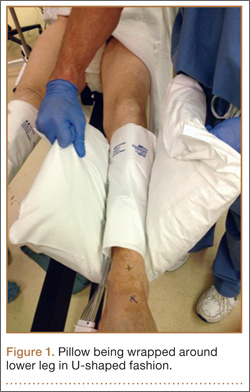
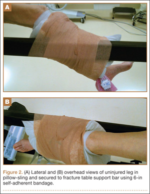
As shown in Figure 3, the C-arm machine can then be positioned in an oblique fashion relative to the bed with an unobstructed view of the hip. The C-arm can also be repositioned perpendicular to the injured limb, and unobstructed images can be obtained of the entire length of the femur. This quick and efficient setup of the well leg allows for an optimal amount of relaxed hip and knee extension, and limb adduction to midline along the table’s support bar, to permit lateral fluoroscopic imaging of the injured limb without overlap of the well leg or interference with C-arm positioning.
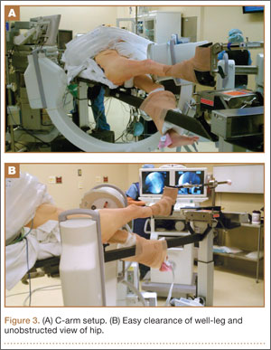
Results
For more than 2 years, Dr. Mir has used the pillow-sling technique for placement of the well leg in the scissored position on the fracture table in all patients. Between September 2010 and January 2013, he applied the technique 93 times, with the procedures listed as follows with their Current Procedural Terminology (CPT) codes: 14 cases of percutaneous fixation of femoral neck fracture (CPT 27235), 8 cases of treatment of intertrochanteric or subtrochanteric fracture with plate/screw type implant (CPT 27244), 34 cases of treatment of intertrochanteric or subtrochanteric fracture with intramedullary implant (CPT 27245), and 37 cases of treatment of femoral shaft fracture with intramedullary implant (CPT 27506).
With respect to compartment syndrome, there were no intraoperative or postoperative complications. Furthermore, no patients complained of pain in the well leg immediately after surgery or at subsequent follow-ups. No difficulty was encountered with intraoperative C-arm imaging of the injured limb at the hip or along the length of the femur in the lateral or anteroposterior planes. The well leg did not have to be repositioned in any cases to achieve adequate imaging of the hip and femur.
Discussion
Although rare, acute compartment syndrome remains a potential yet avoidable complication of the lithotomy position. Some surgeons avoid this setup of the well leg on the fracture table and instead use a scissored position for the uninjured limb.
In this report, we presented a safe and efficient technique for placing the well leg in a scissored position on the fracture table using a pillow and a self-adherent compression bandage. We did not compare the pillow-sling with other well-leg positioning techniques but instead described a reproducible technique that we have used effectively and successfully, even with multiple morbidly obese patients who met the weight limits for the fracture table.
In addition, even with consistent use of this pillow-sling technique at our high-volume trauma center, there have been no complications, such as compartment syndrome, well-leg pain, or difficulty in intraoperative imaging of the injured limb. The pillow-sling is a safe and expedient alternative technique for well-leg positioning on the fracture table, and it can be easily reproduced by other surgeons.
1. Leff RG, Shapiro SR. Lower extremity complications of the lithotomy position: prevention and management. J Urol. 1979;122(1):138-139.
2. Lydon JC, Spielman FJ. Bilateral compartment syndrome following prolonged surgery in the lithotomy position. Anesthesiology. 1984;60(3):236-238.
3. Kubiak R, Wilcox DT, Spitz L, Kiely EM. Neurovascular morbidity from the lithotomy position. J Pediatr Surg. 1998;33(12):1808-1810.
4. Cohen SA, Hurt WG. Compartment syndrome associated with lithotomy position and intermittent compression stockings. Obstet Gynecol. 2001;97(5 pt 2):832-833.
5. Moses TA, Kreder KJ, Thrasher JB. Compartment syndrome: an unusual complication of the lithotomy position. Urology. 1994;43(5):746-747.
6. Chung JH, Ahn KR, Park JH, et al. Lower leg compartment syndrome following prolonged orthopedic surgery in the lithotomy position –A case report–. Korean J Anesthesiol. 2010;59(suppl):S49-S52.
7. Tan V, Pepe MD, Glaser DL, Seldes RM, Heppenstall RB, Esterhai JL Jr. Well-leg compartment pressures during hemilithotomy position for fracture fixation. J Orthop Trauma. 2000;14(3):157-161.
8. Anglen J, Banovetz J. Compartment syndrome in the well leg resulting from fracture-table positioning. Clin Orthop. 1994;(301):239-242.
9. Mathews PV, Perry JJ, Murray PC. Compartment syndrome of the well leg as a result of the hemilithotomy position: a report of two cases and review of literature. J Orthop Trauma. 2001;15(8):580-583.
10. Chase J, Harford F, Pinzur MS, Zussman M. Intraoperative lower extremity compartment pressures in lithotomy-positioned patients. Dis Colon Rectum. 2000;43(5):678-680.
11. Meyer RS, White KK, Smith JM, Groppo ER, Mubarak SJ, Hargens AR. Intramuscular and blood pressures in legs positioned in the hemilithotomy position: clarification of risk factors for well-leg acute compartment syndrome. J Bone Joint Surg Am. 2002;84(10):1829-1835.
12. Enderby GE. Postural ischaemia and blood-pressure. Lancet. 1954;266(6804):185-187.
13. Matsen FA 3rd, Mayo KA, Krugmire RB Jr, Sheridan GW, Kraft GH. A model compartmental syndrome in man with particular reference to the quantification of nerve function. J Bone Joint Surg Am. 1977;59(5):648-653.
14. Peters P, Baker SR, Leopold PW, Taub NA, Burnand KG. Compartment syndrome following prolonged pelvic surgery. Br J Surg. 1994;81(8):1128-1131.
15. Gershuni DH, Yaru NC, Hargens AR, Lieber RL, O’Hara RC, Akeson WH. Ankle and knee position as a factor modifying intracompartmental pressure in the human leg. J Bone Joint Surg Am. 1984;66(9):1415-1420.
The development of acute compartment syndrome in lower legs placed in the lithotomy position is a rare complication reported within various surgical subspecialties, including general surgery, gynecology, and urology.1-5 Although it is reported in arthroscopic knee cases, the more frequent occurrence in orthopedics, based on available case reports, appears to involve the well (uninjured or contralateral) leg placed in the hemilithotomy position on the fracture table.6-9
Prior studies have found significantly elevated lower leg compartment pressures in legs placed in the lithotomy position. Chase and colleagues10 measured the anterior compartment pressures in 16 limbs placed in the lithotomy position. They found minor elevations after initial lithotomy positioning, but gradual increases over time, with an average elevation to 30 mm Hg and maximum of 70 mm Hg. Similarly, Meyer and colleagues11 recorded the lower leg pressures in 8 healthy volunteers positioned on a fracture table. Changing from the supine position to the lithotomy position significantly increased the intramuscular pressure in the anterior compartment (from 11.6 to 19.4 mm Hg) and in the lateral compartment (from 13.0 to 25.8 mm Hg).
Along with increased intramuscular pressures, local hypotension occurs in lower legs placed in the lithotomy position. Mean diastolic blood pressure in the ankle was 63.9 mm Hg in the leg placed in the supine position as opposed to 34.6 mm Hg in the same leg placed in the lithotomy position.10 This finding is not unexpected, given that local arteriolar pressure decreases by 0.78 mm Hg for every 1.0 cm of elevation.12-14 Furthermore, some “kinking” of either femoral vessels at the hip or popliteal vessels at the knee may also occur.15
For prevention of these problems, the well leg can be placed in a position of slight hip extension and full knee extension on the fracture table—the so-called scissored position. This position is commonly achieved with an additional traction boot and support bar connected to the well leg. However, this additional setup can make positioning the C-arm machine difficult; there is obstruction by the additional support bars and the leg itself. In addition, the uninjured extremity may be placed into positions that cause unnecessarily high stresses across the joints and can potentially lead to iatrogenic injury and pain.
Risk of fracture in the well leg results from the C-arm machine abutting the well leg when swinging through to obtain a lateral image. This problem is overcome by securing the well leg to the fracture table’s longitudinal support bar using a pillow sling, thereby reducing the risks of compartment syndrome, allowing the uninjured limb to be in a relaxed position, and allowing good fluoroscopic images to easily be obtained. This brief report is an introduction to this positioning method.
Surgical Technique
The patient is intubated and anesthetized on the hospital bed before being transferred to the fracture table. On the fracture table, the operative leg is placed in a boot traction device in the standard fashion. The perineal post is then inserted, and the patient is pulled caudally on the bed so that the post is appropriately positioned for countertraction.
With an assistant holding the well leg, the distal flat-top table extension is removed. With a calf or foot sequential compression device still in place, a pillow enclosed in a pillowcase is wrapped around the lower leg and ankle in a U-shaped fashion using the longitudinal length of the pillow (Figure 1). The pillow-wrapped leg is then placed against the side (not the top) of the table’s support bar and secured in place using a 6-in self-adherent compression bandage (eg, Coban; 3M, St. Paul, Minnesota), wrapped circumferentially around both the pillow and the support post (Figures 2A, 2B). Although an Ace wrap may be more readily accessible, we have found it to slowly loosen and/or migrate, thus potentially changing the leg position throughout the case.
As shown in Figure 3, the C-arm machine can then be positioned in an oblique fashion relative to the bed with an unobstructed view of the hip. The C-arm can also be repositioned perpendicular to the injured limb, and unobstructed images can be obtained of the entire length of the femur. This quick and efficient setup of the well leg allows for an optimal amount of relaxed hip and knee extension, and limb adduction to midline along the table’s support bar, to permit lateral fluoroscopic imaging of the injured limb without overlap of the well leg or interference with C-arm positioning.
Results
For more than 2 years, Dr. Mir has used the pillow-sling technique for placement of the well leg in the scissored position on the fracture table in all patients. Between September 2010 and January 2013, he applied the technique 93 times, with the procedures listed as follows with their Current Procedural Terminology (CPT) codes: 14 cases of percutaneous fixation of femoral neck fracture (CPT 27235), 8 cases of treatment of intertrochanteric or subtrochanteric fracture with plate/screw type implant (CPT 27244), 34 cases of treatment of intertrochanteric or subtrochanteric fracture with intramedullary implant (CPT 27245), and 37 cases of treatment of femoral shaft fracture with intramedullary implant (CPT 27506).
With respect to compartment syndrome, there were no intraoperative or postoperative complications. Furthermore, no patients complained of pain in the well leg immediately after surgery or at subsequent follow-ups. No difficulty was encountered with intraoperative C-arm imaging of the injured limb at the hip or along the length of the femur in the lateral or anteroposterior planes. The well leg did not have to be repositioned in any cases to achieve adequate imaging of the hip and femur.
Discussion
Although rare, acute compartment syndrome remains a potential yet avoidable complication of the lithotomy position. Some surgeons avoid this setup of the well leg on the fracture table and instead use a scissored position for the uninjured limb.
In this report, we presented a safe and efficient technique for placing the well leg in a scissored position on the fracture table using a pillow and a self-adherent compression bandage. We did not compare the pillow-sling with other well-leg positioning techniques but instead described a reproducible technique that we have used effectively and successfully, even with multiple morbidly obese patients who met the weight limits for the fracture table.
In addition, even with consistent use of this pillow-sling technique at our high-volume trauma center, there have been no complications, such as compartment syndrome, well-leg pain, or difficulty in intraoperative imaging of the injured limb. The pillow-sling is a safe and expedient alternative technique for well-leg positioning on the fracture table, and it can be easily reproduced by other surgeons.
1. Leff RG, Shapiro SR. Lower extremity complications of the lithotomy position: prevention and management. J Urol. 1979;122(1):138-139.
2. Lydon JC, Spielman FJ. Bilateral compartment syndrome following prolonged surgery in the lithotomy position. Anesthesiology. 1984;60(3):236-238.
3. Kubiak R, Wilcox DT, Spitz L, Kiely EM. Neurovascular morbidity from the lithotomy position. J Pediatr Surg. 1998;33(12):1808-1810.
4. Cohen SA, Hurt WG. Compartment syndrome associated with lithotomy position and intermittent compression stockings. Obstet Gynecol. 2001;97(5 pt 2):832-833.
5. Moses TA, Kreder KJ, Thrasher JB. Compartment syndrome: an unusual complication of the lithotomy position. Urology. 1994;43(5):746-747.
6. Chung JH, Ahn KR, Park JH, et al. Lower leg compartment syndrome following prolonged orthopedic surgery in the lithotomy position –A case report–. Korean J Anesthesiol. 2010;59(suppl):S49-S52.
7. Tan V, Pepe MD, Glaser DL, Seldes RM, Heppenstall RB, Esterhai JL Jr. Well-leg compartment pressures during hemilithotomy position for fracture fixation. J Orthop Trauma. 2000;14(3):157-161.
8. Anglen J, Banovetz J. Compartment syndrome in the well leg resulting from fracture-table positioning. Clin Orthop. 1994;(301):239-242.
9. Mathews PV, Perry JJ, Murray PC. Compartment syndrome of the well leg as a result of the hemilithotomy position: a report of two cases and review of literature. J Orthop Trauma. 2001;15(8):580-583.
10. Chase J, Harford F, Pinzur MS, Zussman M. Intraoperative lower extremity compartment pressures in lithotomy-positioned patients. Dis Colon Rectum. 2000;43(5):678-680.
11. Meyer RS, White KK, Smith JM, Groppo ER, Mubarak SJ, Hargens AR. Intramuscular and blood pressures in legs positioned in the hemilithotomy position: clarification of risk factors for well-leg acute compartment syndrome. J Bone Joint Surg Am. 2002;84(10):1829-1835.
12. Enderby GE. Postural ischaemia and blood-pressure. Lancet. 1954;266(6804):185-187.
13. Matsen FA 3rd, Mayo KA, Krugmire RB Jr, Sheridan GW, Kraft GH. A model compartmental syndrome in man with particular reference to the quantification of nerve function. J Bone Joint Surg Am. 1977;59(5):648-653.
14. Peters P, Baker SR, Leopold PW, Taub NA, Burnand KG. Compartment syndrome following prolonged pelvic surgery. Br J Surg. 1994;81(8):1128-1131.
15. Gershuni DH, Yaru NC, Hargens AR, Lieber RL, O’Hara RC, Akeson WH. Ankle and knee position as a factor modifying intracompartmental pressure in the human leg. J Bone Joint Surg Am. 1984;66(9):1415-1420.