User login
NETWORKS: Disaster preparedness. New acronyms. ECS in transplantation. Electronic cigarettes.
Disaster Response
Lessons from Orlando
The recent nightclub shootings in Orlando have forced my colleagues and I at our Level I Trauma Center to reexamine the way we do business. Our typical approach to injury involves resource-intense therapy with a gang of clinicians, while anticipating no more than one or two patients at a time. While this model is excellent for training, we would struggle with the scale of casualties seen in Orlando.
Several observations may be made internally and have been made in the press. Triage should take place prior to the emergency department so that patients are appropriately prioritized to high-intensity support. Fundamental high-impact interventions requiring simple application, such as tourniquets, should be part of the training for all medical and nonmedical first responders. Perhaps most importantly, we need to reexamine the concept that health care is provided by competing geographic and economic entities. Evolution of trauma care has “followed the money” but not necessarily the need. An approach viewing trauma care as a right and acute response as a community resource may be necessary.
In 2008, the Republican Party held its convention in St. Paul, Minn. Reports indicated that 20,000-50,000 individuals were expected to enter the city, including protesters and anarchist groups. We prepared together for events ranging from vehicular crashes to biologic agents or explosive events (Dries et al. J Trauma. 2012; 73[6]:1614). Since then, however, there has been little community-wide planning.
Orlando reminds us that we dare not leave these plans on the shelf.
David Dries, MD, FCCP
Steering Committee Member
Practice Operations
MACRA, QPP, MIPS, APM: Know these acronyms

In October 2015, Congress passed the Medicare Access and CHIP Reauthorization Act of 2015 (MACRA). A bipartisan legislation, it replaces the flawed Sustainable Growth Rate (SGR) formula that would have forced a 21% cut in Medicare payments to clinicians. MACRA established Quality Payment Program (QPP) that has two paths that link quality to payments: the Merit-Based Incentive Payment System (MIPS) or Advanced Alternative Payment Models (APMs).
MIPS streamlines three currently independent programs – (Physician Quality Reporting Program [PQRS], Value-Based Payment Modifier [VM], and Medicare Electronic Health Records Incentive Program) – into a single program in which eligible professions (EPs) will be measured on quality (50%), resource use/cost (10%), clinical practice improvement activities (15%), and advancing care information (25%). The resulting composite performance score (CPS, scale 0-100) is used to determine and apply a +/- or neutral payment adjustment based on a performance threshold. Payment adjustments will begin in 2019 (based on 2017 performance period). Most physicians will be subject to MIPS, which does not apply to hospitals or facilities.
APMs are new approaches to paying for medical care incentivizing quality and value. As defined by MACRA, APMs include CMS Innovation Center models, the Medicare Shared Saving program, and certain demonstration programs. To qualify for payments, the APMs must also use certified EHR technology, report on certain quality measures, and bear more than nominal financial risk.
Both MIPS and APMs are value-based payment models that incentivize providers on quality, outcomes, and cost containment. Most physicians who see Medicare patients will be required to report either the MIPS or Advanced APM track starting in January 2017.
Editor’s Note – See additional article on MACRA on page in this issue.
Adel Bassily-Marcus, MD, FCCP
Vice-Chair
Transplant
Extracorporeal circulatory support in thoracic medicine and surgery – evolving technology and expanding role

There is growing interest in the use of extracorporeal support (ECS) beyond intraoperative and perioperative utility. This has been driven by improvements in safety and efficacy resulting from corresponding technological advances and enhanced user ability. The paucity of donors, however, remains a significant limiting factor in lung transplantation (LT), and there is a growing number of recipients on the waiting list getting too sick for transplantation. ECS is now commonly used to bridge recipients to LT, and reported outcomes show great promise. Indeed, there is even a growing interest in combining ECS with the ex vivo reconditioning of lungs in a further attempt to broaden the donor pool.
This newly developing paradigm constitutes a confluence of contemporary technologies that should allow more marginal or previously unacceptable donor lungs to be procured and also for the use of cardiopulmonary support to bridge sicker recipients safely. As with most technologies, the prerequisite capital outlay, training, and logistical resources will be required to allow for the acquisition of skill and safety. Furthermore, these trends will likely stimulate development of standards and guidelines to ensure a continuing quest for excellence.

The ongoing use of ECS in transplantation has a ripple effect that may prompt its use in other clinical scenarios, such as a rescue therapy in acute exacerbations of COPD, an alternative to mechanical ventilation following complex thoracic pulmonary or esophageal resections, and in cases of unexpected intraoperative cardiopulmonary collapse. One thing remains likely, however, ECS is here to stay.
Jeremiah Hayanga, MD
Steering Committee Member
Norihisa Shigemura, MD
Steering Committee Member
Women’s Health
Exposure of adolescents to electronic cigarettes: still a cause for alarm despite recent FDA ruling

Developed in 2003, electronic cigarettes (e-cigarettes) have been available in the United States since 2007. Between 2010 and 2013, adult use doubled. By 2013, the major tobacco companies had entered the market, and e-cigarettes were marketed widely (television, Internet, and print) as healthier alternatives to tobacco, useful for quitting smoking, and a way to circumvent smoke-free laws by allowing smokers to “smoke anywhere” (Grana et al. Circulation. 2014;129[19]:1972).
For adolescents, e-cigarette use tripled between 2013 and 2014, from 4.5% (660,000) to 13.4% (2 million) for high school students and from 1.1% (120,000) to 3.9% (450,000) for middle school students (CDC Press Release. http://www.cdc.gov/media/releases/2015/p0416-e-cigarette-use.html). Teenage experimentation, in conjunction with susceptibility to brain-modifying effects of nicotine, places this population at risk for lifelong nicotine addiction. Teenagers who use e-cigarettes are more likely to become regular cigarette smokers than nonusers (Dutra et al. JAMA Pediatr. 2014;168[7]:610; Levanthal et al. JAMA. 2015;314[7]:700). Local and state municipalities have enacted legislation, adding e-cigarettes and other electronic nicotine delivery systems (ENDS) to existing tobacco regulations. On May 5, 2016, a long-anticipated ruling from the FDA extended oversight to include all tobacco products, including e-cigarettes and hookahs, allowing the agency to address public health concerns, such as youth access. However, a key provision of the new tobacco “deeming” rules was subsequently removed less than a month later – one that would have removed flavored e-cigarettes, cigars, hookahs, and other flavored tobacco products from the market in November pending review by the Food and Drug Administration (Boyles. MedPage Today. medpagetoday.com/pulmonology/smoking/58274).

ENDS as a smoking cessation tool, a “safer” alternative to combustible tobacco, is much debated (Green et al. N Engl J Med. 2016;374[14]:1301). There is accumulating evidence of its in vivo and in vitro toxicity (Bhatnagar et al. Circulation. 2014;130[16]:1418; Gibbs et al. Chest. 2016;149[2]:552). Studies have shown that the varied concentration and flavorings used are cytotoxic to human embryonic stem cells as well as mice neural stem cells (Bahl et al. Reprod Toxicol. 2012[4];34:529) and that exposure to propylene glycol and glycerin, main base ingredients in e-liquids, can result in eye and respiratory irritation (Grana et al. Circulation. 2014; 129[19]:1972). Additionally, current evidence does not support e-cigarettes for smoking cessation (Grana et al. Circulation. 2014;129[19]:1972). The accumulating evidence of adverse effects and the increased use in adolescents underscores the need for stricter regulations by the FDA in order to prevent renormalization of the smoking behavior and to protect public health. The rollout of the FDA’s ruling will warrant ongoing evaluation.
Linda S. Efferen, MD, MBA
Consultant
Amanpreet Kaur, MD
Steering Committee Member
Disaster Response
Lessons from Orlando
The recent nightclub shootings in Orlando have forced my colleagues and I at our Level I Trauma Center to reexamine the way we do business. Our typical approach to injury involves resource-intense therapy with a gang of clinicians, while anticipating no more than one or two patients at a time. While this model is excellent for training, we would struggle with the scale of casualties seen in Orlando.
Several observations may be made internally and have been made in the press. Triage should take place prior to the emergency department so that patients are appropriately prioritized to high-intensity support. Fundamental high-impact interventions requiring simple application, such as tourniquets, should be part of the training for all medical and nonmedical first responders. Perhaps most importantly, we need to reexamine the concept that health care is provided by competing geographic and economic entities. Evolution of trauma care has “followed the money” but not necessarily the need. An approach viewing trauma care as a right and acute response as a community resource may be necessary.
In 2008, the Republican Party held its convention in St. Paul, Minn. Reports indicated that 20,000-50,000 individuals were expected to enter the city, including protesters and anarchist groups. We prepared together for events ranging from vehicular crashes to biologic agents or explosive events (Dries et al. J Trauma. 2012; 73[6]:1614). Since then, however, there has been little community-wide planning.
Orlando reminds us that we dare not leave these plans on the shelf.
David Dries, MD, FCCP
Steering Committee Member
Practice Operations
MACRA, QPP, MIPS, APM: Know these acronyms
In October 2015, Congress passed the Medicare Access and CHIP Reauthorization Act of 2015 (MACRA). A bipartisan legislation, it replaces the flawed Sustainable Growth Rate (SGR) formula that would have forced a 21% cut in Medicare payments to clinicians. MACRA established Quality Payment Program (QPP) that has two paths that link quality to payments: the Merit-Based Incentive Payment System (MIPS) or Advanced Alternative Payment Models (APMs).
MIPS streamlines three currently independent programs – (Physician Quality Reporting Program [PQRS], Value-Based Payment Modifier [VM], and Medicare Electronic Health Records Incentive Program) – into a single program in which eligible professions (EPs) will be measured on quality (50%), resource use/cost (10%), clinical practice improvement activities (15%), and advancing care information (25%). The resulting composite performance score (CPS, scale 0-100) is used to determine and apply a +/- or neutral payment adjustment based on a performance threshold. Payment adjustments will begin in 2019 (based on 2017 performance period). Most physicians will be subject to MIPS, which does not apply to hospitals or facilities.
APMs are new approaches to paying for medical care incentivizing quality and value. As defined by MACRA, APMs include CMS Innovation Center models, the Medicare Shared Saving program, and certain demonstration programs. To qualify for payments, the APMs must also use certified EHR technology, report on certain quality measures, and bear more than nominal financial risk.
Both MIPS and APMs are value-based payment models that incentivize providers on quality, outcomes, and cost containment. Most physicians who see Medicare patients will be required to report either the MIPS or Advanced APM track starting in January 2017.
Editor’s Note – See additional article on MACRA on page in this issue.
Adel Bassily-Marcus, MD, FCCP
Vice-Chair
Transplant
Extracorporeal circulatory support in thoracic medicine and surgery – evolving technology and expanding role
There is growing interest in the use of extracorporeal support (ECS) beyond intraoperative and perioperative utility. This has been driven by improvements in safety and efficacy resulting from corresponding technological advances and enhanced user ability. The paucity of donors, however, remains a significant limiting factor in lung transplantation (LT), and there is a growing number of recipients on the waiting list getting too sick for transplantation. ECS is now commonly used to bridge recipients to LT, and reported outcomes show great promise. Indeed, there is even a growing interest in combining ECS with the ex vivo reconditioning of lungs in a further attempt to broaden the donor pool.
This newly developing paradigm constitutes a confluence of contemporary technologies that should allow more marginal or previously unacceptable donor lungs to be procured and also for the use of cardiopulmonary support to bridge sicker recipients safely. As with most technologies, the prerequisite capital outlay, training, and logistical resources will be required to allow for the acquisition of skill and safety. Furthermore, these trends will likely stimulate development of standards and guidelines to ensure a continuing quest for excellence.
The ongoing use of ECS in transplantation has a ripple effect that may prompt its use in other clinical scenarios, such as a rescue therapy in acute exacerbations of COPD, an alternative to mechanical ventilation following complex thoracic pulmonary or esophageal resections, and in cases of unexpected intraoperative cardiopulmonary collapse. One thing remains likely, however, ECS is here to stay.
Jeremiah Hayanga, MD
Steering Committee Member
Norihisa Shigemura, MD
Steering Committee Member
Women’s Health
Exposure of adolescents to electronic cigarettes: still a cause for alarm despite recent FDA ruling
Developed in 2003, electronic cigarettes (e-cigarettes) have been available in the United States since 2007. Between 2010 and 2013, adult use doubled. By 2013, the major tobacco companies had entered the market, and e-cigarettes were marketed widely (television, Internet, and print) as healthier alternatives to tobacco, useful for quitting smoking, and a way to circumvent smoke-free laws by allowing smokers to “smoke anywhere” (Grana et al. Circulation. 2014;129[19]:1972).
For adolescents, e-cigarette use tripled between 2013 and 2014, from 4.5% (660,000) to 13.4% (2 million) for high school students and from 1.1% (120,000) to 3.9% (450,000) for middle school students (CDC Press Release. http://www.cdc.gov/media/releases/2015/p0416-e-cigarette-use.html). Teenage experimentation, in conjunction with susceptibility to brain-modifying effects of nicotine, places this population at risk for lifelong nicotine addiction. Teenagers who use e-cigarettes are more likely to become regular cigarette smokers than nonusers (Dutra et al. JAMA Pediatr. 2014;168[7]:610; Levanthal et al. JAMA. 2015;314[7]:700). Local and state municipalities have enacted legislation, adding e-cigarettes and other electronic nicotine delivery systems (ENDS) to existing tobacco regulations. On May 5, 2016, a long-anticipated ruling from the FDA extended oversight to include all tobacco products, including e-cigarettes and hookahs, allowing the agency to address public health concerns, such as youth access. However, a key provision of the new tobacco “deeming” rules was subsequently removed less than a month later – one that would have removed flavored e-cigarettes, cigars, hookahs, and other flavored tobacco products from the market in November pending review by the Food and Drug Administration (Boyles. MedPage Today. medpagetoday.com/pulmonology/smoking/58274).
ENDS as a smoking cessation tool, a “safer” alternative to combustible tobacco, is much debated (Green et al. N Engl J Med. 2016;374[14]:1301). There is accumulating evidence of its in vivo and in vitro toxicity (Bhatnagar et al. Circulation. 2014;130[16]:1418; Gibbs et al. Chest. 2016;149[2]:552). Studies have shown that the varied concentration and flavorings used are cytotoxic to human embryonic stem cells as well as mice neural stem cells (Bahl et al. Reprod Toxicol. 2012[4];34:529) and that exposure to propylene glycol and glycerin, main base ingredients in e-liquids, can result in eye and respiratory irritation (Grana et al. Circulation. 2014; 129[19]:1972). Additionally, current evidence does not support e-cigarettes for smoking cessation (Grana et al. Circulation. 2014;129[19]:1972). The accumulating evidence of adverse effects and the increased use in adolescents underscores the need for stricter regulations by the FDA in order to prevent renormalization of the smoking behavior and to protect public health. The rollout of the FDA’s ruling will warrant ongoing evaluation.
Linda S. Efferen, MD, MBA
Consultant
Amanpreet Kaur, MD
Steering Committee Member
Catching up with our past presidents
Where are they now? What have they been up to? CHEST’s Past Presidents each forged the way for the many successes of the American College of Chest Physicians (CHEST), leading to enhanced patient care around the globe. Their outstanding leadership and vision are evidenced today in many of CHEST’s current initiatives, and now it is time to check in with these past leaders to give us a look at what’s new.
Alex G. Little, MD, FCCP
President 1990-1991
Being President of the American College of Chest Physicians was a remarkable and exhilarating experience beginning with my inauguration in San Francisco in 1990. Although I had been active with the College for several years, the responsibility of the presidency entailed a much closer relationship with the organization, the excellent staff, the physician leaders, the greater membership, and notably, Dr. Al Soffer. As the Executive Director, Al was my go to advisor and guide for questions and advice. He and his wife Izzy became good personal friends and that relationship is one of the major benefits of my presidency (although it never resulted in him showing any mercy on the tennis courts).

For me, as a surgeon, one of the appealing aspects of the College, and, in particular, its annual meeting, was its interdisciplinary nature with pulmonologists, surgeons, and cardiologists interacting in a way that more narrowly focused specialty societies rarely provide. Learning alternative perspectives and hearing from other disciplines is always interesting and occasionally critically important for progress toward maximal patient care.
During my tenure, there were several noteworthy events. The College continued to exhibit robust growth in membership, strengthening its role in supporting chest physicians. We opened the new (amazingly, now the old) headquarters building in Northbrook, signaling a commitment to remain state of the art and joined the challenge of providing continuing medical education for our members.
I retired from clinical practice and as Chair of Surgery at Wright State in 2010 when my wife Louise and I settled in Tucson. I am involved with teaching and mentoring general and cardiothoracic residents at the University of Arizona and also keep active with ongoing clinical research projects. With my leisure time, I play tennis, read books I should have gotten to in earlier years, look for a publisher for a book I have written on the evolution of thoracic surgery (for the general reader), and admire my wife’s expertise in making glass beads and jewelry.
Where are they now? What have they been up to? CHEST’s Past Presidents each forged the way for the many successes of the American College of Chest Physicians (CHEST), leading to enhanced patient care around the globe. Their outstanding leadership and vision are evidenced today in many of CHEST’s current initiatives, and now it is time to check in with these past leaders to give us a look at what’s new.
Alex G. Little, MD, FCCP
President 1990-1991
Being President of the American College of Chest Physicians was a remarkable and exhilarating experience beginning with my inauguration in San Francisco in 1990. Although I had been active with the College for several years, the responsibility of the presidency entailed a much closer relationship with the organization, the excellent staff, the physician leaders, the greater membership, and notably, Dr. Al Soffer. As the Executive Director, Al was my go to advisor and guide for questions and advice. He and his wife Izzy became good personal friends and that relationship is one of the major benefits of my presidency (although it never resulted in him showing any mercy on the tennis courts).
For me, as a surgeon, one of the appealing aspects of the College, and, in particular, its annual meeting, was its interdisciplinary nature with pulmonologists, surgeons, and cardiologists interacting in a way that more narrowly focused specialty societies rarely provide. Learning alternative perspectives and hearing from other disciplines is always interesting and occasionally critically important for progress toward maximal patient care.
During my tenure, there were several noteworthy events. The College continued to exhibit robust growth in membership, strengthening its role in supporting chest physicians. We opened the new (amazingly, now the old) headquarters building in Northbrook, signaling a commitment to remain state of the art and joined the challenge of providing continuing medical education for our members.
I retired from clinical practice and as Chair of Surgery at Wright State in 2010 when my wife Louise and I settled in Tucson. I am involved with teaching and mentoring general and cardiothoracic residents at the University of Arizona and also keep active with ongoing clinical research projects. With my leisure time, I play tennis, read books I should have gotten to in earlier years, look for a publisher for a book I have written on the evolution of thoracic surgery (for the general reader), and admire my wife’s expertise in making glass beads and jewelry.

A MACRA primer
Most physicians realize that the specter of the Sustainable Growth Rate (SGR) has been replaced by a “new plan” enacted by Congress under the guise of the Medicare Access and CHIP Reauthorization Act (MACRA) of 2015. A major goal of the programs defined by MACRA is to provide quality care while improving value, the Quality Payment Program (QPP). There are currently two paths for reimbursement from which physicians may choose defined by QPP: the Merit-based Incentive Payment System (MIPS) or the Advanced Alternative Payment Models (APMs). These will be explained in general terms but it would benefit all health-care professionals to visit the CMS website for additional details on the program.
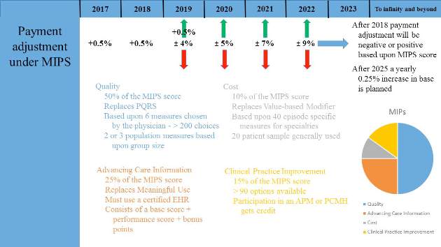
Most physicians will initially choose MIPS by default as most do not currently participate in programs that qualify as APMs. MIPS will eventually result in the demise of the multiple reporting systems presently used by CMS to include the Physician Quality Reporting System (PQRS), the Value-Based Modifier (VBM) Program, and the Medicare Electronic Health Record (EHR) Incentive Program (Meaningful Use). These will be streamlined into a single program, although many of the components are carried through to MIPS (Fig. 1).
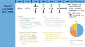
Data from health-care providers will be collected through a variety of sources beginning in January 2017 and this will be used to determine the MIPS score as briefly outlined by the colored text in Figure 1. The 2017 data will determine the MIPS Composite Performance Score (CPS). From 2017 through 2019, CMS will provide a 0.5% increase in payment for services. Between 2020 and 2025, no increase is planned, but starting in 2026, a yearly 0.25% increase in reimbursement is planned. In 2019, physician payment will be adjusted positively or negatively by 4% based upon their MIPS CPS and a threshold CPS determined for all participants. This adjustment will be revenue-neutral, so for every winner there will be a corresponding loser based upon one’s MIPS score. However, there is a scaling factor built into the system for years 2019 to 2024, using up to $500 million to reward those whose CPS are at the highest levels. This adjustment will increase to 5% in 2020, 7% in 2021, and 9% from 2022 onward. Eligible providers can participate as an individual or as a group.
The Advanced Alternative Payment Model, as defined by MACRA, may include a CMS Innovation Center model, MSSP (Medicare Shared Savings Program), Demonstration under the Health Care Quality Demonstration Program, or Demonstration required by federal law. To be an eligible APM requires that these entities: require participants to use certified EHR technology; base payment on quality measures comparable to those in the MIPS quality performance category; either require APM entities to bear more than nominal financial risk for monetary losses; or be a Medical Home Model expanded under Center for Medicare and Medicaid Innovation authority.
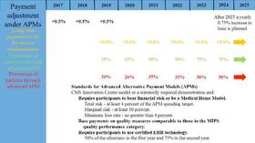
To become a qualifying participant (QP) one must have either a percentage of payments or a percentage of patients through an eligible APM. CMS will calculate a threshold score using Medicare Part B data for professional services and payments in that APM. The percentage of each is illustrated in Figure 2 and will increase from 2019 to 2024. 2017 will be the first year eligible participants will be assessed to determine whether they qualify. If an eligible participant qualifies, year 2018 base payments will be used to determine year 2019 lump sum payment. This is set at 5%. This cycle will continue each year to determine if the participant qualifies for the lump sum distribution. In addition, qualified APMs will receive a yearly 0.75% increase in base payments starting in year 2026. If one participates in an APM but does not meet the threshold for QP set by CMS, one receives either no payment adjustment or may opt to participate in MIPS. Beginning in 2021, CMS may count data from other non-Medicare payers to determine eligibility as a QP.
The goal of the Quality Payment Program is to change the way Medicare pays clinicians and to offer financial incentives for providing high value care. Physicians will be required to participate in either the MIPS or APM programs unless they are in their first year of Part B participation or have a low volume of patients. The program will almost certainly continue to change as input is received from many stakeholders, most importantly health-care professionals and patients. Physicians are, therefore, encouraged to learn more about the program to maximize your reimbursement.
Most physicians realize that the specter of the Sustainable Growth Rate (SGR) has been replaced by a “new plan” enacted by Congress under the guise of the Medicare Access and CHIP Reauthorization Act (MACRA) of 2015. A major goal of the programs defined by MACRA is to provide quality care while improving value, the Quality Payment Program (QPP). There are currently two paths for reimbursement from which physicians may choose defined by QPP: the Merit-based Incentive Payment System (MIPS) or the Advanced Alternative Payment Models (APMs). These will be explained in general terms but it would benefit all health-care professionals to visit the CMS website for additional details on the program.
Most physicians will initially choose MIPS by default as most do not currently participate in programs that qualify as APMs. MIPS will eventually result in the demise of the multiple reporting systems presently used by CMS to include the Physician Quality Reporting System (PQRS), the Value-Based Modifier (VBM) Program, and the Medicare Electronic Health Record (EHR) Incentive Program (Meaningful Use). These will be streamlined into a single program, although many of the components are carried through to MIPS (Fig. 1).
Data from health-care providers will be collected through a variety of sources beginning in January 2017 and this will be used to determine the MIPS score as briefly outlined by the colored text in Figure 1. The 2017 data will determine the MIPS Composite Performance Score (CPS). From 2017 through 2019, CMS will provide a 0.5% increase in payment for services. Between 2020 and 2025, no increase is planned, but starting in 2026, a yearly 0.25% increase in reimbursement is planned. In 2019, physician payment will be adjusted positively or negatively by 4% based upon their MIPS CPS and a threshold CPS determined for all participants. This adjustment will be revenue-neutral, so for every winner there will be a corresponding loser based upon one’s MIPS score. However, there is a scaling factor built into the system for years 2019 to 2024, using up to $500 million to reward those whose CPS are at the highest levels. This adjustment will increase to 5% in 2020, 7% in 2021, and 9% from 2022 onward. Eligible providers can participate as an individual or as a group.
The Advanced Alternative Payment Model, as defined by MACRA, may include a CMS Innovation Center model, MSSP (Medicare Shared Savings Program), Demonstration under the Health Care Quality Demonstration Program, or Demonstration required by federal law. To be an eligible APM requires that these entities: require participants to use certified EHR technology; base payment on quality measures comparable to those in the MIPS quality performance category; either require APM entities to bear more than nominal financial risk for monetary losses; or be a Medical Home Model expanded under Center for Medicare and Medicaid Innovation authority.
To become a qualifying participant (QP) one must have either a percentage of payments or a percentage of patients through an eligible APM. CMS will calculate a threshold score using Medicare Part B data for professional services and payments in that APM. The percentage of each is illustrated in Figure 2 and will increase from 2019 to 2024. 2017 will be the first year eligible participants will be assessed to determine whether they qualify. If an eligible participant qualifies, year 2018 base payments will be used to determine year 2019 lump sum payment. This is set at 5%. This cycle will continue each year to determine if the participant qualifies for the lump sum distribution. In addition, qualified APMs will receive a yearly 0.75% increase in base payments starting in year 2026. If one participates in an APM but does not meet the threshold for QP set by CMS, one receives either no payment adjustment or may opt to participate in MIPS. Beginning in 2021, CMS may count data from other non-Medicare payers to determine eligibility as a QP.
The goal of the Quality Payment Program is to change the way Medicare pays clinicians and to offer financial incentives for providing high value care. Physicians will be required to participate in either the MIPS or APM programs unless they are in their first year of Part B participation or have a low volume of patients. The program will almost certainly continue to change as input is received from many stakeholders, most importantly health-care professionals and patients. Physicians are, therefore, encouraged to learn more about the program to maximize your reimbursement.
Something for everyone: LA cuisine, clinical education at CHEST 2016
Los Angeles is famous for its eclectic mix of palate-pleasing dining options. Chic cafes; international flavors; vegan eateries; and local, coastal cuisine are all readily available. When CHEST 2016 travels to Los Angeles in October, we know you’ll satisfy your taste buds and your educational needs.
With so many options to choose from, here are some recommendations from our favorite Los Angeles locals – CHEST members – to help you plan out your menu:
• LA Prime, 35th floor of the Westin Bonaventure Hotel (6-minute drive): Famous for prime beef steaks, seafood, and panoramic city views. Located at 404 S. Figueroa St, Los Angeles, CA 90071
• Water Grill (6-minute drive): This seafood restaurant is sustainably minded and provides a wide array of delicately prepared seafood in a relaxed, elegant space. Located at 544 S. Grand Ave, Los Angeles, CA 90071
• Pacific Dining Car (7-minute drive): Dine on steak in a railway dining car atmosphere at this iconic restaurant open 24 hours a day every day of the year. Located at 1310 W. 6th St, Los Angeles, CA 90017
• Sticky Rice (7-minute drive): Inside Grand Central Market, enjoy Thai “comfort food” with an emphasis on organic, free-range, and locally sourced seasonal ingredients. Located at 317 S. Broadway, Los Angeles, CA 90013
• Mexicali Taco & Co (9-minute drive): Enjoy mouthwatering Baja style Mexican food, reasonable prices, and a casual dining experience. Located at 702 N. Figueroa St, Los Angeles, CA 90012
• Crossroads Kitchen (22-minute drive): Courtesy of Oprah’s former chef Tal Ronnen, this upscale eatery provides an elegant backdrop for refined vegan dishes paired with wines and cocktails. Located at 8284 Melrose Ave, Los Angeles, CA 90046
• The Sky Room in Long Beach (33-minute drive): This hotel bar/eatery offers New American fare and city views, plus music and dancing on weekends. Located at 40 S. Locust Ave, Long Beach, CA 90802
Looking for a quick bite? Here are some options within walking distance to the convention center:
• Yardhouse (5-minute walk): Find the craft beer you’re looking for while benefiting from a large, diverse menu. Located at 800 W. Olympic Blvd, Los Angeles, CA 90015
• Tom’s Urban (1-minute walk): Enjoy a sprawling gastropub featuring an all-day American menu, large draft beers, and sports on big screens. Located at 1011 S. Figueroa St, Los Angeles, CA 90015
• TASTE Food Hall FIGat7th (4-minute walk): Walk over to Figueroa and 7th, and you’ll find a large food court complete with unique flavor profiles that are shaping the contemporary Los Angeles culinary landscape. Located at 735 S. Figueroa St, Los Angeles, CA 90017
Los Angeles is sure to satisfy your inner foodie with its wide variety of culinary options. From October 22 to 26, CHEST 2016 will also offer you a variety of educational options including postgraduate courses, simulation and interactive learning, interdisciplinary programs, problem-based learning sessions, keynotes and honor lectures, industry supported sessions, and more. CHEST 2016 is dedicated to delivering the latest information in pulmonary, critical care, and sleep medicine to you, ensuring you make the best decisions with your patients. Register by August 31 to pay the lowest fees. Learn more at chestmeeting.chestnet.org.
MOC 10-year assessment
The American Board of Internal Medicine (ABIM) has responded to physicians’ and other stakeholders’ input regarding the Maintenance of Certification (MOC) 10-year assessment and will begin offering an alternate option in January 2018. The new option will include shorter assessments taken more frequently that will be able to be completed from a physician’s office or home. These shorter assessments will identify knowledge gaps, so physicians can tailor their continuing education in order to stay current in knowledge and practice. Successful performance on the shorter assessments will allow physicians to opt out of the longer 10-year exam. The program will be piloted for Internal Medicine and select subspecialties and, based on feedback, will be extended to additional subspecialties at a later date.
Physicians whose certifications expire prior to the new assessment option becoming available will need to pass the current exam in order to maintain certification but then will not need to take another assessment for 10 years.
ABIM’s full announcement can be viewed at abim.org/news/abim-announces-plans-to-offer-physicians-moc-assessment-options-in-january-2018.aspx.
Any questions regarding this development should be directed to the ABIM by visiting www.abim.org/contact.
CHEST Clinical Trials Registry announcement
A new clinical trial is now available in the CHEST Clinical Trials Registry (SENSCISTM, or Safety and Efficacy of Nintedanib in Systemic SClerosIS), a double-blind, randomized, placebo-controlled trial evaluating efficacy and safety of oral nintedanib treatment for at least 52 weeks in patients with Systemic Sclerosis-associated Interstitial Lung Disease (SSc-ILD). The CHEST Clinical Trials Registry is a free service that connects physicians to information about clinical trials in respiratory disease, conducted by participating pharmaceutical companies. To learn more about the registry and how to participate in this clinical trial, please visit www.chestnet.org/Guidelines-and-Resources/Clinical-Trials/Clinical-Trials-Registry.
A new clinical trial is now available in the CHEST Clinical Trials Registry (SENSCISTM, or Safety and Efficacy of Nintedanib in Systemic SClerosIS), a double-blind, randomized, placebo-controlled trial evaluating efficacy and safety of oral nintedanib treatment for at least 52 weeks in patients with Systemic Sclerosis-associated Interstitial Lung Disease (SSc-ILD). The CHEST Clinical Trials Registry is a free service that connects physicians to information about clinical trials in respiratory disease, conducted by participating pharmaceutical companies. To learn more about the registry and how to participate in this clinical trial, please visit www.chestnet.org/Guidelines-and-Resources/Clinical-Trials/Clinical-Trials-Registry.
A new clinical trial is now available in the CHEST Clinical Trials Registry (SENSCISTM, or Safety and Efficacy of Nintedanib in Systemic SClerosIS), a double-blind, randomized, placebo-controlled trial evaluating efficacy and safety of oral nintedanib treatment for at least 52 weeks in patients with Systemic Sclerosis-associated Interstitial Lung Disease (SSc-ILD). The CHEST Clinical Trials Registry is a free service that connects physicians to information about clinical trials in respiratory disease, conducted by participating pharmaceutical companies. To learn more about the registry and how to participate in this clinical trial, please visit www.chestnet.org/Guidelines-and-Resources/Clinical-Trials/Clinical-Trials-Registry.
This Month in CHEST: Editor’s Picks
COMMENTARY
Establishing Pulmonary and Critical Care Medicine in China: 2016 Report on Implementation and Government Recognition: Joint Statement of the Chinese Association of Chest Physicians and the American College of Chest Physicians.
By Dr. Renli Qiao et al, on behalf of the China-CHEST PCCM Program Steering Committee.
CONTEMPORARY REVIEWS IN SLEEP MEDICINE
Cancer and OSA: Current Evidence From Human Studies. By Dr. M. A. Martinez-Garcia et al.
ORIGINAL RESEARCH
Association Between Occupational Exposures and Sarcoidosis: An Analysis From Death Certificates in the United States, 1988-1999. By Dr. H. Liu et al.
Nonlinear Imputation of PaO2/FIO2 From SpO2/FIO2 Among Patients With Acute Respiratory Distress Syndrome. By Dr. S. M. Brown et al.
Blood Eosinophils and Outcomes in Severe Hospitalized Exacerbations of COPD. By Dr. M. Bafadhel et al.
A Randomized Controlled Trial of a Novel Sheath Cryoprobe for Bronchoscopic Lung Biopsy in a Porcine Model. By Dr. L. B. Yarmus et al.
Updated Patient Education guides available
The CHEST Foundation continues to look for new ways to expand our patient education offerings. With the collaboration of the CHEST Foundation’s Patient Education Work Group, the Allergy & Asthma NetWork, and CHEST’s NetWorks, we have completely revamped Living Well With COPD and Living Well With Asthma (previously titled Controlling Your Asthma). At less than 30 pages each, the guides are more user-friendly, featuring multiple diagrams to supplement instructions, take-away glossaries, easy-to-read infographics, and new FAQs.
The guides are available to order in packs of 25 in the CHEST store. Packs are $50 for members and $62.50 for nonmembers. The new guides are available for viewing online at chestnet.org/asthmainfo and chestnet.org/copdinfo.
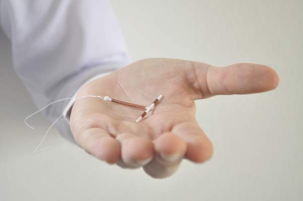
Lidocaine gel doesn’t relieve IUD insertion pain but cuts need for dilation
While vaginal lidocaine gel does not significantly reduce pain from intrauterine device (IUD) insertion, it does appear to reduce the pain from tenaculum placement in nulliparous women and the likelihood that women will need cervical dilation for insertion, according to the results of a randomized controlled trial.
Despite the effectiveness of IUDs in preventing pregnancy, some women don’t choose this contraception method because they fear the pain of insertion, past research has found. Pain is also more likely in women who have not given birth. In fact, just 5.9% of nulliparous women use IUDs, compared with 16.8% of women with one or two prior births, wrote Rachel B. Rapkin, MD, MPH, of the University of South Florida in Tampa, and her colleagues (Obstet Gynecol. 2016;128:621-8. doi: 10.1097/AOG.0000000000001596).
The researchers tested the effectiveness of self-administered lidocaine gel as pain relief with 59 nulliparous women aged 14-50 years from University of Pittsburgh Medical Center clinics between July 2012 and May 2013. All of the women requested an IUD. A total of 30 women were randomized to apply the 2% lidocaine vaginal gel 5 minutes before the IUD insertion. Another 29 women were randomized to apply a placebo gel. Nearly all the women reported that inserting the gel was somewhat or very easy and that they had no pain after insertion.
There was one unsuccessful IUD insertion in the placebo group. That woman had intolerable pain while attempting uterine sound so the procedure was aborted. She was included in the intention-to-treat analysis with all missing data set to 100 mm on a 100-mm visual analog scale.
In the intention-to-treat analysis, the median change in pain from baseline to IUD insertion was 61 mm for women who used the lidocaine gel. Women using placebo reported a median score of 69 mm, which was not significantly different from those using the lidocaine gel (P = .06). However, women using lidocaine did report significantly less pain when the tenaculum was placed: a median 32 mm on the pain scale, compared with 56 mm reported by those who used the placebo gel (P = .02).
Although 87% of the physicians reported that insertion was easy in the women with lidocaine, compared with 64% who said it was easy in women using the placebo gel, the difference was not significant (P = .07). However, significantly more women needed cervical dilation before IUD placement if they used the placebo (34.5%), compared with those using the lidocaine (3.3%, P = .002). The women also reported pain scores after speculum placement, uterine sounding, and 5 minutes after speculum removal, but none of these showed significant differences.
Overall, more than one-third of the women needed to take pain medication for at least 3 days after the IUD was inserted, but the majority of women (86%) would probably or definitely recommend an IUD to a friend, and 76% reported satisfaction with the insertion experience. Cramping and pain medication use after insertion did not vary between the two groups.
The generalizability of the trial may be limited because it enrolled participants who were largely white and college educated and it used clinicians with at least 4 years of IUD insertion experience.
The research was funded by the Society of Family Planning Research Fund. Dr. Rapkin reported having no financial disclosures. Her coauthors reported consulting work for Merck and research funding from Bayer Healthcare and Medicines 360 Inc. One of the coauthors is founder and president of the nonprofit Basic Health International.
FROM OBSTETRICS & GYNECOLOGY
Key clinical point: Vaginal lidocaine gel does not decrease IUD insertion pain but decreases likelihood of needing cervical dilation.
Major finding: More than a third of women using placebo gel required cervical dilation before IUD placement, compared with 3.3% of women using lidocaine gel (P = .002).
Data source: The findings are based on a randomized, double-blind, placebo-controlled trial involving 59 nulliparous women between July 2012 and May 2013.
Disclosures: The research was funded by the Society of Family Planning Research Fund. Dr. Rapkin reported having no financial disclosures. Her coauthors reported consulting work for Merck and research funding from Bayer Healthcare and Medicines 360 Inc. One of the coauthors is founder and president of the nonprofit Basic Health International.

Lipid Screening in Young Adults Still Unsettled
The value of screening young adults for dyslipidemia remains unknown because there is still no direct evidence regarding the benefits and harms in this patient population, according to an update of the 2008 U.S. Preventive Services Task Force recommendations on lipid screening, which was published online August 8 in Annals of Internal Medicine.
In 2008, the USPSTF also could find no direct evidence regarding asymptomatic men and women aged 21-39 years, and thus could make no recommendation for or against lipid screening “because of the low likelihood of identifying lipid levels high enough to justify treatment.” Now the organization has undertaken an extensive review of all English-language articles released since then, searching the Cochrane Central Register of Controlled Trials, the Cochrane Database of Systematic Reviews, Medline, reference lists, and ClinicalTrials.gov, said Roger Chou, MD, lead author of the update and director of the Pacific Northwest Evidence-Based Practice Center, Oregon Health & Science University, Portland, and his associates.

They were unable to find any randomized trials, cohort studies, or case-control studies comparing lipid screening against no lipid screening, dyslipidemia treatment against no treatment, or immediate against delayed treatment that assessed mortality, cardiovascular outcomes, or harms in this age group.
Some health organizations recommend starting dyslipidemia screening in asymptomatic adults at age 20, while others don’t recommend the practice until age 35-40 for men and age 50 for women. The 2014 American College of Cardiology/American Heart Association guideline on assessing CV risk deems it “reasonable” to assess traditional risk factors including lipids beginning at age 20, Dr. Chou and his associates said (Ann Intern Med. 2016 Aug 8. doi: 10.7326/M16-0946).
However, the potential adverse effects of statin therapy that is initiated in young adulthood and continued for decades haven’t been well studied, they noted.
In addition, some experts advocate lipid screening to identify young adults who have familial hypercholesterolemia. But this condition has such a low prevalence (estimated at only 1 in 500 people), and affected patients have such a low rate of coronary heat disease events before age 40 (approximately 10%) that the potential benefits of screening for this reason are very limited, the investigators added.
This study was supported by the Agency for Healthcare Research and Quality.
The value of screening young adults for dyslipidemia remains unknown because there is still no direct evidence regarding the benefits and harms in this patient population, according to an update of the 2008 U.S. Preventive Services Task Force recommendations on lipid screening, which was published online August 8 in Annals of Internal Medicine.
In 2008, the USPSTF also could find no direct evidence regarding asymptomatic men and women aged 21-39 years, and thus could make no recommendation for or against lipid screening “because of the low likelihood of identifying lipid levels high enough to justify treatment.” Now the organization has undertaken an extensive review of all English-language articles released since then, searching the Cochrane Central Register of Controlled Trials, the Cochrane Database of Systematic Reviews, Medline, reference lists, and ClinicalTrials.gov, said Roger Chou, MD, lead author of the update and director of the Pacific Northwest Evidence-Based Practice Center, Oregon Health & Science University, Portland, and his associates.
They were unable to find any randomized trials, cohort studies, or case-control studies comparing lipid screening against no lipid screening, dyslipidemia treatment against no treatment, or immediate against delayed treatment that assessed mortality, cardiovascular outcomes, or harms in this age group.
Some health organizations recommend starting dyslipidemia screening in asymptomatic adults at age 20, while others don’t recommend the practice until age 35-40 for men and age 50 for women. The 2014 American College of Cardiology/American Heart Association guideline on assessing CV risk deems it “reasonable” to assess traditional risk factors including lipids beginning at age 20, Dr. Chou and his associates said (Ann Intern Med. 2016 Aug 8. doi: 10.7326/M16-0946).
However, the potential adverse effects of statin therapy that is initiated in young adulthood and continued for decades haven’t been well studied, they noted.
In addition, some experts advocate lipid screening to identify young adults who have familial hypercholesterolemia. But this condition has such a low prevalence (estimated at only 1 in 500 people), and affected patients have such a low rate of coronary heat disease events before age 40 (approximately 10%) that the potential benefits of screening for this reason are very limited, the investigators added.
This study was supported by the Agency for Healthcare Research and Quality.
FROM ANNALS OF INTERNAL MEDICINE
