User login
Exertional Heat Stroke and American Football: What the Team Physician Needs to Know
Football, one of the most popular sports in the United States, is additionally recognized as a leading contributor to sports injury secondary to the contact collision nature of the endeavor. There are an estimated 1.1 million high school football players with another 100,000 participants combined in the National Football League (NFL), college, junior college, Arena Football League, and semipro levels of play.1 USA Football estimates that an additional 3 million youth participate in community football leagues.1 The National Center for Catastrophic Sports Injury Research recently calculated a fatality rate of 0.14 per 100,000 participants in 2014 for the 4.2 million who play football at all levels—and 0.45 per 100,000 in high school.1 While direct deaths from head and spine injury remain a significant contributor to the number of catastrophic injuries, indirect deaths (systemic failure) predominate. Exertional heat stroke (EHS) has emerged as one of the leading indirect causes of death in high school and collegiate football. Boden and colleagues2 reported that high school and college football players sustain approximately 12 fatalities annually, with indirect systemic causes being twice as common as direct blunt trauma.2The most common indirect causes identified included cardiac failure, heat illness, and complications of sickle cell trait (SCT). It was also noted that the risk of SCT, heat-related, and cardiac deaths increased during the second decade of the study, indicating these conditions may require a greater emphasis on diagnosis, treatment, and prevention. This review details for the team physician the unique challenge of exercising in the heat to the football player, and the prevention, diagnosis, management and return-to-play issues pertinent to exertional heat illness (EHI).
The Challenge
EHS represents the most severe manifestation of EHI—a gamut of diseases commonly encountered during the hot summer months when American football season begins. The breadth of EHI includes several important clinical diagnoses: exercise-associated muscle cramps (heat cramps); heat exhaustion with and without syncope; heat injury with evidence of end organ injury (eg, rhabdomyolysis); and EHS. EHS is defined as “a form of hyperthermia associated with a systemic inflammatory response leading to a syndrome of multi-organ dysfunction in which encephalopathy predominates.”3 EHS, if left untreated, or even if clinical treatment is delayed, may result in significant end organ morbidity and/or mortality.
During exercise, the human thermoregulatory system mitigates heat gain by increasing skin blood flow and sweating, causing an increased dissipation of heat to the surrounding environment by leveraging conduction, convection, and evaporation.4,5 Elevated environmental temperatures, increased humidity, and dehydration can impede the body’s ability to dissipate heat at a rate needed to maintain thermoregulation. This imbalance can result in hyperthermia secondary to uncompensated heat stress,5 which in turn can lead to EHI. Football players have unique challenges that make them particularly vulnerable to EHI. The summer heat during early-season participation and the requirement for equipment that covers nearly 60% of body surfaces pose increased risk of volume losses and hyperthermia that trigger the onset of EHI.6 Football athletes’ body compositions and physical size are additional contributing risk factors; the relatively high muscle and fat content increase thermogenicity, which require their bodies to dissipate more heat.7
An estimated 9000 cases of EHI occur annually across all high school sports,8 with an incidence of 1.6:100,000 athlete-exposures.8,9 Studies have demonstrated, however, that EHI occurs in football 11.4 times more often than in all other high school sports combined.10 The incidence of nonfatal EHI in all levels of football is 4.42-5:100,000.8,9 Between 2000 and 2014, 41 football players died from EHS.1 In football, approximately 75% of all EHI events occurred during practices, while only 25% of incidents occurred during games.8
Given these potentially deadly consequences, it is important that football team physicians are not only alert to the early symptoms of heat illness and prepared to intervene to prevent the progression to EHS, but are critical leaders in educating coaches and players in evidence-based EHI prevention practices and policies.
Prevention
EHS is a preventable condition, arguably the most common cause of preventable nontraumatic exertional death in young athletes in the United States. Close attention to mitigating risk factors should begin prior to the onset of preseason practice and continue through the early season, where athletes are at the highest risk of developing heat illness.
Primary Prevention
Primary prevention is fundamental to minimizing the occurrences of EHI. It focuses on the following methods: recognition of inherent risk factors, acclimatization, hydration, and avoidance of inciting substances (including supplements).
Pre-Participation Examination. The purpose of the pre-participation examination (PPE) is to maximize an athlete’s safety by identifying medical conditions that place the athlete at risk.11,12 The Preparticipation Physical Evaluation, 4th edition, the most widely used consensus publication, specifically queries if an athlete has a previous history of heat injury. However, it only indirectly addresses intrinsic risk factors that may predispose an athlete to EHI who has never had an EHI before. Therefore, providers should take the opportunity of the PPE to inquire about additional risk factors that may make an athlete high risk for sustaining a heat injury. Common risk factors for EHI are listed in Table 1. 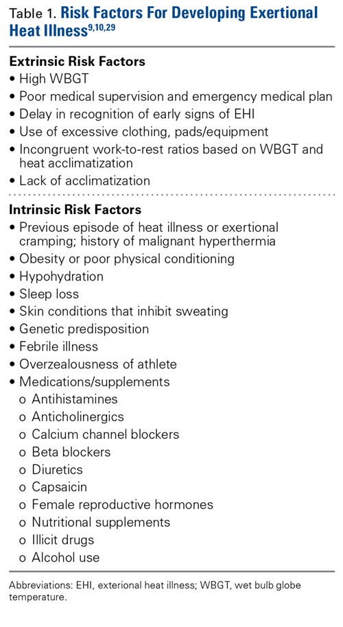
Heat Acclimatization. The risk of EHI escalates significantly when athletes are subjected to multiple stressors during periods of heat exposure, such as sudden increases in intensity or duration of exercise; prolonged new exposures to heat; dehydration; and sleep loss.5 When football season begins in late summer, athletes are least conditioned as temperatures reach their seasonal peak, causing increased risk of EHI.15 Planning for heat acclimatization is vital for all athletes who exercise in hot environments. Acclimatization procedures place progressively mounting physiologic strains on the body to improve athletes’ ability to dissipate heat, diminishing thermoregulatory and cardiovascular exertion.4,5 Acclimatization begins with expansion of plasma volume on days 3 to 6, causing improvements in cardiac efficiency and resulting in an overall decrease in basal internal body temperature.4,5,15 This process results in improvements in heat tolerance and exercise performance, evolving over 10 to 14 days of gradual escalation of exercise intensity and duration.5,10,11,16 However, poor fitness levels and extreme temperatures can prolong this period, requiring up to 2 to 3 months to fully take effect.5,7
The National Athletic Trainers Association (NATA) and National Collegiate Athletic Association (NCAA) have released consensus guidelines regarding heat acclimatization protocols for football athletes at the high school and college levels (Tables 3 and 4). Each of these guidelines involves an initial period without use of protective equipment, followed by a gradual addition of further equipment.11,16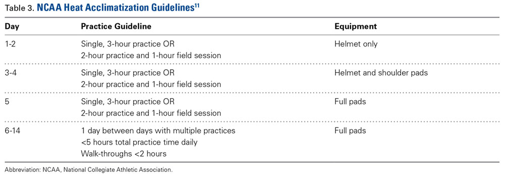
Secondary Prevention
Despite physicians’ best efforts to prevent all cases of EHI, athletes will still experience the effects of exercise-induced hyperthermia. The goal of secondary prevention is to slow the progression of this hyperthermia so that it does not progress to more dangerous EHI.
Hydration. Dehydration is an important risk factor for EHI. Sweat maintains thermoregulation by dissipating heat generated during exercise; however, it also contributes to body water losses. Furthermore, intravascular depletion decreases stroke volume, thereby increasing cardiovascular strain. It is estimated that for every 1% loss in body mass from dehydration, body temperature rises 0.22°C in comparison to a euhydrated state.6 Dehydration occurs more rapidly in hot environments, as fluid is lost through increased sweat production.7 After approximately 6% to 10% body weight volume loss, cardiac output cannot be maintained, diminishing sweat production and blood flow to both skin and muscle and causing diminished performance and a significant risk of heat exhaustion.7 If left unchecked, these physiologic changes result in further elevations in body temperature and increased cardiovascular strain, ultimately placing the athlete at significant risk for development of EHS.
Adequate hydration to maintain euvolemia is an important step in avoiding possible EHI. Multiple studies have shown that football players experience a baseline hypovolemia during their competition season,6 a deficit that is most marked during the first week of practices.17 This deficit is multifactorial, as football players expend a significant amount of fluid through sweat, are not able to adequately replace these losses during practice, and do not appropriately hydrate off the field.6,18 Some players, especially linemen, sweat at a higher rate than their teammates, posing a possible risk of significant dehydration.6 Coaches and players alike should be educated on the importance of adequate hydration to meet their fluid needs.
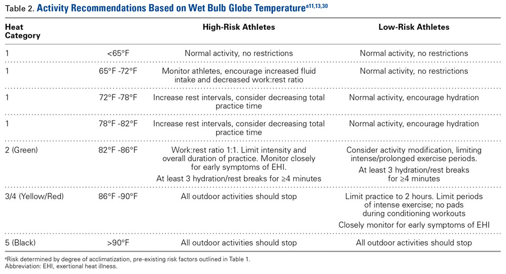
The goal of hydration during exercise is to prevent large fluid losses that can adversely affect performance and increase risk of EHI;6 it may be unrealistic to replace all fluid losses during the practice period. Instead, athletes should target complete volume replacement over the post-exercise period.6 Some recommend hydrating based upon thirst drive; however, thirst is activated following a volume loss of approximately 2% body mass, the same degree of losses that place athletes at an increased risk for performance impairment and EHI.4,6,11,12 Individuals should have access to fluids throughout practice and competition and be encouraged to hydrate as needed.6,12,15 Furthermore, staff should modify their practices based upon WBGT and acclimatization status to provide more frequent hydration breaks.
Hyperhydration and Salt Intake. Of note, there are inherent risks to hyperhydration. Athletes with low sweat rates have an increased risk of overhydration and the development of exercise-associated hyponatremia (EAH),6 a condition whose presentation is very similar to EHS. In addition, inadequate sodium intake and excessive sweating can also contribute to the development of EAH. EAH has been implicated in the deaths of 2 football players in 2014.1,6 Establishing team hydration guidelines and educating players and staff on appropriate hydration and dietary salt intake is essential to reduce the risk of both dehydration and hyperhydration and their complications.6Intra-Event Cooling. During exercise, team physicians can employ strategies for cooling athletes during exertion to mitigate their risk of EHI by decreasing thermal and cardiovascular strain.4,19 Cooling during exercise is hypothesized to allow for accelerated heat dissipation, where heat is lost from the body more effectively. This accelerated loss enables athletes to maintain a higher heat storage capacity over the duration of exercise, avoiding uncompensated heat stresses that ultimately cause EHI.19
Some intra-event cooling strategies include the use of cooling garments, cooling packs, and cold water/slurry ingestion. Cooling garments lower skin temperature, which in turn can decrease thermoregulatory strains;4 a recent meta-analysis of intra-event cooling modalities revealed that wearing an ice vest during exercise resulted in the greatest decrease in thermal heat strain.19 Internal cooling strategies—namely ingestion of cold fluids/ice slurry—have shown some mild benefit in decreasing internal temperatures; however, some studies have demonstrated some decrease in sweat production associated with cold oral intake used in isolation.19 Overall, studies have shown that combining external (cooling clothing, ice packs, fanning) and internal (cold water, ice slurry) cooling methods result in a greater cooling effect than a use of a single method.4
Tertiary Prevention
The goal of tertiary prevention is to mitigate the risk of long-term adverse outcomes following an EHS event. The most effective means of reducing risk for morbidity and mortality is rapid identification and treatment of EHS as well as close evaluation of an athlete’s return to activity in heat. This process is spearheaded by an effective and well-rehearsed emergency action plan.
Diagnosis and Management
Rapid identification and treatment of EHS is crucial to minimizing the risk of poor outcomes.7 Any delay in the treatment of EHS can dramatically increase the likelihood of associated morbidity and mortality.20
EHS is diagnosed by an elevated rectal temperature ≥40°C (104°F) and associated central nervous system (CNS) dysfunction.21 EHS should be strongly suspected in any athlete exercising in heat who exhibits signs of CNS dysfunction, including disorientation, confusion, dizziness, erratic behavior, irritability, headache, loss of coordination, delirium, collapse, or seizures.7,12,15 EHS may also present with symptoms of heat exhaustion, including fatigue, hyperventilation, tachycardia, vomiting, diarrhea, and hypotension.7,12,15
Rectal temperature should be taken for any athlete with suspected EHS, as other modalities—oral, skin, axillary, and aural—can be inaccurate and easily modified by ambient confounders such as ambient and skin temperature, athlete hyperventilation, and consumption of liquids.7,11,12 Athletes exhibiting CNS symptoms with moderately elevated rectal temperatures that do not exceed 40°C should also be assumed to be suffering from EHS and treated with rapid cooling.11 On the other hand, athletes with CNS symptoms who are normothermic should be assumed to have EAH until ruled out by electrolyte assessment; IV fluids should be at no more than keep vein open (KVO) pending this determination.11 In some cases, an athlete may initially present with altered mental status but return to “normal.” However, this improvement may represent a “lucid period”; evaluation should continue with rectal temperature and treatment, as EHS in these cases may progress quickly.15
Treatment is centered on rapid, whole body cooling initiated at the first sign of heat illness.7,22 The goal of treatment is to achieve a rectal temperature <38.9°C within 30 minutes of the onset of EHS.15 Upon diagnosis, the athlete should be quickly placed in a tub of ice water to facilitate cold water immersion (CWI) therapy. Some guidelines suggest the athlete’s clothing be removed to potentiate evaporative cooling during CWI;12 however, cooling should not be delayed due to difficulties in removing equipment. CWI, where a heat stroke victim is submerged in ice water up to their neck while water is continuously circulated, is generally considered to be the gold standard treatment as it is the modality with the highest recorded cooling rates and the lowest rate of morbidity and mortality.7,20,21 Multiple studies of CWI have shown that survival nears 100% when aggressive cooling starts within 5 minutes of collapse or identification of EHS.20,21,22
If whole body CWI is unavailable, alternative methods of rapid cooling should be employed. Partial CWI, with torso immersion being preferable to the extremities, has been shown to achieve an acceptable rate of cooling to achieve sufficient drops in internal body temperature.20,23 However, one popular treatment—applying ice packs to the whole body, in particular to the groin and axillae—has not been shown to be sufficient to achieve standard cooling goals.20 None of these methods have been shown to be as effective as CWI.23
Intravenous access should be initiated with fluid resuscitation dictated by the provider’s assessment. Normal saline is recommended as the resuscitative fluid of choice, with the rate dictated by clinical judgment and adjusted as guided by electrolyte determination and clinical response. It cannot be overstated that in normothermic patients with confusion, EAH is the diagnosis of exclusion and aggressive fluid resuscitation should be withheld until electrolyte determination.
Once rectal temperature descends appropriately (~38.9°C), the cooling process should stop and the individual should be transported to a hospital for further observation20 and evaluation of possible sequelae, including rhabdomyolysis and renal injury, cardiac dysfunction and arrhythmia, severe electrolyte abnormalities, acute respiratory distress syndrome, lactic acidosis, and other forms of end-organ failure (Figure).
Rapid cooling is more crucial than transport; transport poses a risk of delayed cooling, which can dramatically increase an individual’s risk of morbidity and mortality.20,23 In situations where a patient can be cooled on-site, physicians should pursue cooling before transporting the patient to a medical treatment facility.
Emergency Action Plan
Team physicians should be proactive in developing an emergency action plan to address possible EHS events. These plans should be site-specific, addressing procedures for all practice and home competition locations.12 All competition venues should have a CWI tub on-site in events where there is an increased risk of EHS.12,15,20 This tub should be set up and functional for all high-risk activities, including practices.12
Following recognition of a potential case of EHS, treatment teams should have procedures in place to transport athletes to the treatment area, obtain rectal temperature, initiate rapid cooling, and stabilize the athlete for transport to an emergency department (ED) for further evaluation.12,15 A written record of treatments and medications provided during athlete stabilization should be maintained and transported with the athlete to the ED.15 A list of helpful equipment and supplies for treatment of EHS can be found in Table 5.
EHS is a unique life-threatening situation where it is best to treat the patient on the sideline before transport.15 Those athletes transported before cooling risk spending an increased amount of time above critical temperatures for cell damage, which has been associated with increased morbidity and mortality. This mantra of “cool first, transport second” cannot be overemphasized, as those individuals with EHS who present to the ED with a persisting rectal temperature >41°F may risk up to an 80% mortality rate.24 Conversely, a recent large, retrospective study of 274 EHS events sustained during the Falmouth Road Race found a 100% survival rate when athletes were rapidly identified via rectal thermometry and treated with aggressive, rapid cooling through CWI.21
Return to Play
Perhaps the most challenging and important role the team physician has is determining an athlete’s return to play following EHI, as there currently are no evidence-based guidelines for return to activity for these athletes.7 The decisions surrounding return to play are highly individualized, as recovery from EHS and heat injury is associated with the duration of internal body temperature elevation above the critical level (40°C).7,20 Guidelines for return to activity following recovery from EHI differ among experts and institutions.7,25 The general consensus from these guidelines is that, at minimum, athletes should not participate in any physical activity until they are asymptomatic and all blood tests have normalized.11 Following this asymptomatic period, most guidelines advocate for a slow, deliberate return to activity.11 The American College of Sports Medicine (ACSM) offers one reasonable approach to the returning athlete following EHS:7
- No exercise for at least 7 days following release from medical care.
- Follow-up with a physician 1 week after release from medical care for physical examination and any warranted lab or radiologic studies (based upon organ systems affected during EHS).
- Once cleared to return to activity, the athlete begins exercise in a cool environment, gradually increasing the duration, intensity, and heat exposure over 2 weeks to demonstrate heat tolerance and acclimatization.
- Athletes who cannot resume vigorous activity due to recurrent symptoms (eg, excessive fatigue) should be reevaluated after 4 weeks. Laboratory exercise-heat tolerance testing may be useful in this setting.
- The athlete may resume full competition once they are able to participate in full training in the heat for 2 to 4 weeks without adverse effects.
Heat tolerance testing (HTT) in these athletes remains controversial.5 26 The ACSM recommends that HTT be considered only for those unable to return to vigorous activity after a suitable period (approximately 4 weeks). In contrast, the Israeli Defense Force (IDF) uses HTT to evaluate soldiers following EHS to guide decision-making about return to duty.27 The IDF HTT assumes that individuals will respond differently to heat stresses. They identify individuals who are “heat intolerant” as being unable to tolerate specific heat challenges, indicated by increases in body temperature occurring more rapidly than normal responders under identical environmental and exercise conditions. However, despite being used for more than 30 years, there is no clear evidence that HTT adequately predicts who will experience subsequent episodes of EHS.
Conclusion
While the recognized cornerstone of being a team physician is the provision of medical care, the ACSM Team Physician Consensus Statement28 further delineates the medical and administrative responsibilities as both (1) understanding medical management and prevention of injury and illness in athletes; and (2) awareness of or involvement in the development and rehearsal of an emergency action plan. These tenets are critical for the team physician who accepts the responsibility to cover sports at the high school level or higher. Football team physicians play an essential role in mitigating risk of EHI in their athletes. Through development and execution of both comprehensive prevention strategies and emergency action plans, physicians can work to minimize athletes’ risk of both developing and experiencing significant adverse outcomes from an EHI.
Am J Orthop. 2016;45(6):340-348. Copyright Frontline Medical Communications Inc. 2016. All rights reserved.
1. Kucera KL, Klossner D, Colgate B, Cantu RC. Annual Survey of Football Injury Research: 1931-2014. National Center for Catastrophic Sport Injury Research Web site. https://nccsir.unc.edu/files/2013/10/Annual-Football-2014-Fatalities-Final.pdf. Accessed May 31, 2016.
2. Boden BP, Breit I, Beachler JA, Williams A, Mueller FO. Fatalities in high school and college football players. Am J Sports Med. 2013;41(5):1108-1116.
3. Bouchama A, Knochel JP. Heat stroke. N Engl J Med. 2002;346(25):1978-1988.
4. Racinais S, Alonso JM, Coutts AJ, et al. Consensus recommendations on training and competing in the heat. Scand J Med Sci Sports. 2015;25 Suppl 1:6-19.
5. Pryor RR, Casa DJ, Adams WM, et al. Maximizing athletic performance in the heat. Strength Cond J. 2013;35(6):24-33.
6. Adams WM, Casa DJ. Hydration for football athletes. Sports Sci Exchange. 2015;28(141):1-5.
7. American College of Sports Medicine, Armstrong LE, Casa DJ, et al. American College of Sports Medicine position stand. Exertional heat illness during training and competition. Med Sci Sports Exerc. 2007;39(3):556-572.
8. Yard EE, Gilchrist J, Haileyesus T, et al. Heat illness among high school athletes--United States, 2005-2009. J Safety Res. 2010;41(6):471-474.
9. Huffman EA, Yard EE, Fields SK, Collins CL, Comstock RD. Epidemiology of rare injuries and conditions among United States high school athletes during the 2005-2006 and 2006-2007 school years. J Athl Train. 2008;43(6):624-630.
10. Kerr ZY, Casa DJ, Marshall SW, Comstock RD. Epidemiology of exertional heat illness among U.S. high school athletes. Am J Prev Med. 2013;44(1):8-14.
11. Casa DJ, DeMartini JK, Bergeron MF, et al. National Athletic Trainers’ Association position statement: exertional heat illnesses. J Athl Train. 2015;50(9):986-1000.
12. Casa DJ, Almquist J, Anderson SA. The inter-association task force for preventing sudden death in secondary school athletics programs: best-practices recommendations. J Athl Train. 2013;48(4):546-553.
13. Gardner JW, Kark JA, Karnei K, et al. Risk factors predicting exertional heat illness in male Marine Corps recruits. Med Sci Sports Exerc. 1996;28(8):939-944.
14. Gundstein AJ, Ramseyer C, Zhao F, et al. A retrospective analysis of American football hyperthermia deaths in the United States. Int J Biometerol. 2012;56(1):11-20.
15. Armstrong LE, Johnson EC, Casa DJ, et al. The American football uniform: uncompensable heat stress and hyperthermic exhaustion. J Athl Train. 2010;45(2):117-127.
16. Casa DJ, Csillan D; Inter-Association Task Force for Preseason Secondary School Athletics Participants, et al. Preseason heat-acclimatization guidelines for secondary school athletics. J Athl Train. 2009;44(3):332-333.
17. Godek SF, Godek JJ, Bartolozzi AR. Hydration status in college football players during consecutive days of twice-a-day preseason practices. Am J Sports Med. 2005;33(6):843-851.
18. Stover EA, Zachwieja J, Stofan J, Murray R, Horswill CA. Consistently high urine specific gravity in adolescent American football players and the impact of an acute drinking strategy. Int J Sports Med. 2006;27(4):330-335.
19. Bongers CC, Thijssen DH, Veltmeijer MTW, Hopman MT, Eijsvogels TM. Precooling and percooling (cooling during exercise) both improve performance in the heat: a meta-analytical review. Br J Sports Med. 2015;49(6):377-384.
20. Casa DJ, McDermott BP, Lee EC, Yeargin SW, Armstrong LE, Maresh CM. Cold water immersion: the gold standard for exertional heatstroke treatment. Exerc Sport Sci Rev. 2007;35(3):141-149.
21. DeMartini JK, Casa DJ, Stearns R, et al. Effectiveness of cold water immersion in the treatment of exertional heat stroke at the Falmouth Road Race. Med Sci Sports Exerc. 2015;47(2):240-245.
22. Casa DJ, Kenny GP, Taylor NA. Immersion treatment for exertional hyperthermia: cold or temperate water? Med Sci Sports Exerc. 2010;42(7):1246-1252.
23. Casa DJ, Armstrong LE, Kenny GP, O’Connor FG, Huggins RA. Exertional heat stroke: new concepts regarding cause and care. Curr Sports Med Rep. 2012;11(3):115-122.
24. Argaud L, Ferry T, Le QH, et al. Short- and long-term outcomes of heat stroke following the 2003 heat wave in Lyon, France. Arch Intern Med. 2007;167(20):2177-2183.
25. O’Connor FG, Casa DJ, Bergeron MF, et al. American College of Sports Medicine Roundtable on exertional heat stroke--return to duty/return to play: conference proceedings. Curr Sports Med Rep. 2010;9(5):314-321.
26. Kazman JB, Heled Y, Lisman PJ, Druyan A, Deuster PA, O’Connor FG. Exertional heat illness: the role of heat tolerance testing. Curr Sports Med Rep. 2013;12(2):101-105.
27. Moran DS, Heled Y, Still L, Laor A, Shapiro Y. Assessment of heat tolerance for post exertional heat stroke individuals. Med Sci Monit. 2004;10(6):CR252-CR257.
28. Herring SA, Kibler WB, Putukian M. Team Physician Consensus Statement: 2013 update. Med Sci Sports Exerc. 2013;45(8):1618-1622.
29. Heat stroke treatment. Korey Stringer Institute University of Connecticut Web site. http://ksi.uconn.edu/emergency-conditions/heat-illnesses/exertional-heat-stroke/heat-stroke-treatment/. Accessed June 14, 2016.
30. Headquarters, Department of the Army and the Air Force. Heat Stress Control and Heat Casualty Management. Technical Bulletin Medical 507. http://www.dir.ca.gov/oshsb/documents/Heat_illness_prevention_tbmed507.pdf. Published March 7, 2003. Accessed June 14, 2016.
Football, one of the most popular sports in the United States, is additionally recognized as a leading contributor to sports injury secondary to the contact collision nature of the endeavor. There are an estimated 1.1 million high school football players with another 100,000 participants combined in the National Football League (NFL), college, junior college, Arena Football League, and semipro levels of play.1 USA Football estimates that an additional 3 million youth participate in community football leagues.1 The National Center for Catastrophic Sports Injury Research recently calculated a fatality rate of 0.14 per 100,000 participants in 2014 for the 4.2 million who play football at all levels—and 0.45 per 100,000 in high school.1 While direct deaths from head and spine injury remain a significant contributor to the number of catastrophic injuries, indirect deaths (systemic failure) predominate. Exertional heat stroke (EHS) has emerged as one of the leading indirect causes of death in high school and collegiate football. Boden and colleagues2 reported that high school and college football players sustain approximately 12 fatalities annually, with indirect systemic causes being twice as common as direct blunt trauma.2The most common indirect causes identified included cardiac failure, heat illness, and complications of sickle cell trait (SCT). It was also noted that the risk of SCT, heat-related, and cardiac deaths increased during the second decade of the study, indicating these conditions may require a greater emphasis on diagnosis, treatment, and prevention. This review details for the team physician the unique challenge of exercising in the heat to the football player, and the prevention, diagnosis, management and return-to-play issues pertinent to exertional heat illness (EHI).
The Challenge
EHS represents the most severe manifestation of EHI—a gamut of diseases commonly encountered during the hot summer months when American football season begins. The breadth of EHI includes several important clinical diagnoses: exercise-associated muscle cramps (heat cramps); heat exhaustion with and without syncope; heat injury with evidence of end organ injury (eg, rhabdomyolysis); and EHS. EHS is defined as “a form of hyperthermia associated with a systemic inflammatory response leading to a syndrome of multi-organ dysfunction in which encephalopathy predominates.”3 EHS, if left untreated, or even if clinical treatment is delayed, may result in significant end organ morbidity and/or mortality.
During exercise, the human thermoregulatory system mitigates heat gain by increasing skin blood flow and sweating, causing an increased dissipation of heat to the surrounding environment by leveraging conduction, convection, and evaporation.4,5 Elevated environmental temperatures, increased humidity, and dehydration can impede the body’s ability to dissipate heat at a rate needed to maintain thermoregulation. This imbalance can result in hyperthermia secondary to uncompensated heat stress,5 which in turn can lead to EHI. Football players have unique challenges that make them particularly vulnerable to EHI. The summer heat during early-season participation and the requirement for equipment that covers nearly 60% of body surfaces pose increased risk of volume losses and hyperthermia that trigger the onset of EHI.6 Football athletes’ body compositions and physical size are additional contributing risk factors; the relatively high muscle and fat content increase thermogenicity, which require their bodies to dissipate more heat.7
An estimated 9000 cases of EHI occur annually across all high school sports,8 with an incidence of 1.6:100,000 athlete-exposures.8,9 Studies have demonstrated, however, that EHI occurs in football 11.4 times more often than in all other high school sports combined.10 The incidence of nonfatal EHI in all levels of football is 4.42-5:100,000.8,9 Between 2000 and 2014, 41 football players died from EHS.1 In football, approximately 75% of all EHI events occurred during practices, while only 25% of incidents occurred during games.8
Given these potentially deadly consequences, it is important that football team physicians are not only alert to the early symptoms of heat illness and prepared to intervene to prevent the progression to EHS, but are critical leaders in educating coaches and players in evidence-based EHI prevention practices and policies.
Prevention
EHS is a preventable condition, arguably the most common cause of preventable nontraumatic exertional death in young athletes in the United States. Close attention to mitigating risk factors should begin prior to the onset of preseason practice and continue through the early season, where athletes are at the highest risk of developing heat illness.
Primary Prevention
Primary prevention is fundamental to minimizing the occurrences of EHI. It focuses on the following methods: recognition of inherent risk factors, acclimatization, hydration, and avoidance of inciting substances (including supplements).
Pre-Participation Examination. The purpose of the pre-participation examination (PPE) is to maximize an athlete’s safety by identifying medical conditions that place the athlete at risk.11,12 The Preparticipation Physical Evaluation, 4th edition, the most widely used consensus publication, specifically queries if an athlete has a previous history of heat injury. However, it only indirectly addresses intrinsic risk factors that may predispose an athlete to EHI who has never had an EHI before. Therefore, providers should take the opportunity of the PPE to inquire about additional risk factors that may make an athlete high risk for sustaining a heat injury. Common risk factors for EHI are listed in Table 1.
Heat Acclimatization. The risk of EHI escalates significantly when athletes are subjected to multiple stressors during periods of heat exposure, such as sudden increases in intensity or duration of exercise; prolonged new exposures to heat; dehydration; and sleep loss.5 When football season begins in late summer, athletes are least conditioned as temperatures reach their seasonal peak, causing increased risk of EHI.15 Planning for heat acclimatization is vital for all athletes who exercise in hot environments. Acclimatization procedures place progressively mounting physiologic strains on the body to improve athletes’ ability to dissipate heat, diminishing thermoregulatory and cardiovascular exertion.4,5 Acclimatization begins with expansion of plasma volume on days 3 to 6, causing improvements in cardiac efficiency and resulting in an overall decrease in basal internal body temperature.4,5,15 This process results in improvements in heat tolerance and exercise performance, evolving over 10 to 14 days of gradual escalation of exercise intensity and duration.5,10,11,16 However, poor fitness levels and extreme temperatures can prolong this period, requiring up to 2 to 3 months to fully take effect.5,7
The National Athletic Trainers Association (NATA) and National Collegiate Athletic Association (NCAA) have released consensus guidelines regarding heat acclimatization protocols for football athletes at the high school and college levels (Tables 3 and 4). Each of these guidelines involves an initial period without use of protective equipment, followed by a gradual addition of further equipment.11,16
Secondary Prevention
Despite physicians’ best efforts to prevent all cases of EHI, athletes will still experience the effects of exercise-induced hyperthermia. The goal of secondary prevention is to slow the progression of this hyperthermia so that it does not progress to more dangerous EHI.
Hydration. Dehydration is an important risk factor for EHI. Sweat maintains thermoregulation by dissipating heat generated during exercise; however, it also contributes to body water losses. Furthermore, intravascular depletion decreases stroke volume, thereby increasing cardiovascular strain. It is estimated that for every 1% loss in body mass from dehydration, body temperature rises 0.22°C in comparison to a euhydrated state.6 Dehydration occurs more rapidly in hot environments, as fluid is lost through increased sweat production.7 After approximately 6% to 10% body weight volume loss, cardiac output cannot be maintained, diminishing sweat production and blood flow to both skin and muscle and causing diminished performance and a significant risk of heat exhaustion.7 If left unchecked, these physiologic changes result in further elevations in body temperature and increased cardiovascular strain, ultimately placing the athlete at significant risk for development of EHS.
Adequate hydration to maintain euvolemia is an important step in avoiding possible EHI. Multiple studies have shown that football players experience a baseline hypovolemia during their competition season,6 a deficit that is most marked during the first week of practices.17 This deficit is multifactorial, as football players expend a significant amount of fluid through sweat, are not able to adequately replace these losses during practice, and do not appropriately hydrate off the field.6,18 Some players, especially linemen, sweat at a higher rate than their teammates, posing a possible risk of significant dehydration.6 Coaches and players alike should be educated on the importance of adequate hydration to meet their fluid needs.
The goal of hydration during exercise is to prevent large fluid losses that can adversely affect performance and increase risk of EHI;6 it may be unrealistic to replace all fluid losses during the practice period. Instead, athletes should target complete volume replacement over the post-exercise period.6 Some recommend hydrating based upon thirst drive; however, thirst is activated following a volume loss of approximately 2% body mass, the same degree of losses that place athletes at an increased risk for performance impairment and EHI.4,6,11,12 Individuals should have access to fluids throughout practice and competition and be encouraged to hydrate as needed.6,12,15 Furthermore, staff should modify their practices based upon WBGT and acclimatization status to provide more frequent hydration breaks.
Hyperhydration and Salt Intake. Of note, there are inherent risks to hyperhydration. Athletes with low sweat rates have an increased risk of overhydration and the development of exercise-associated hyponatremia (EAH),6 a condition whose presentation is very similar to EHS. In addition, inadequate sodium intake and excessive sweating can also contribute to the development of EAH. EAH has been implicated in the deaths of 2 football players in 2014.1,6 Establishing team hydration guidelines and educating players and staff on appropriate hydration and dietary salt intake is essential to reduce the risk of both dehydration and hyperhydration and their complications.6Intra-Event Cooling. During exercise, team physicians can employ strategies for cooling athletes during exertion to mitigate their risk of EHI by decreasing thermal and cardiovascular strain.4,19 Cooling during exercise is hypothesized to allow for accelerated heat dissipation, where heat is lost from the body more effectively. This accelerated loss enables athletes to maintain a higher heat storage capacity over the duration of exercise, avoiding uncompensated heat stresses that ultimately cause EHI.19
Some intra-event cooling strategies include the use of cooling garments, cooling packs, and cold water/slurry ingestion. Cooling garments lower skin temperature, which in turn can decrease thermoregulatory strains;4 a recent meta-analysis of intra-event cooling modalities revealed that wearing an ice vest during exercise resulted in the greatest decrease in thermal heat strain.19 Internal cooling strategies—namely ingestion of cold fluids/ice slurry—have shown some mild benefit in decreasing internal temperatures; however, some studies have demonstrated some decrease in sweat production associated with cold oral intake used in isolation.19 Overall, studies have shown that combining external (cooling clothing, ice packs, fanning) and internal (cold water, ice slurry) cooling methods result in a greater cooling effect than a use of a single method.4
Tertiary Prevention
The goal of tertiary prevention is to mitigate the risk of long-term adverse outcomes following an EHS event. The most effective means of reducing risk for morbidity and mortality is rapid identification and treatment of EHS as well as close evaluation of an athlete’s return to activity in heat. This process is spearheaded by an effective and well-rehearsed emergency action plan.
Diagnosis and Management
Rapid identification and treatment of EHS is crucial to minimizing the risk of poor outcomes.7 Any delay in the treatment of EHS can dramatically increase the likelihood of associated morbidity and mortality.20
EHS is diagnosed by an elevated rectal temperature ≥40°C (104°F) and associated central nervous system (CNS) dysfunction.21 EHS should be strongly suspected in any athlete exercising in heat who exhibits signs of CNS dysfunction, including disorientation, confusion, dizziness, erratic behavior, irritability, headache, loss of coordination, delirium, collapse, or seizures.7,12,15 EHS may also present with symptoms of heat exhaustion, including fatigue, hyperventilation, tachycardia, vomiting, diarrhea, and hypotension.7,12,15
Rectal temperature should be taken for any athlete with suspected EHS, as other modalities—oral, skin, axillary, and aural—can be inaccurate and easily modified by ambient confounders such as ambient and skin temperature, athlete hyperventilation, and consumption of liquids.7,11,12 Athletes exhibiting CNS symptoms with moderately elevated rectal temperatures that do not exceed 40°C should also be assumed to be suffering from EHS and treated with rapid cooling.11 On the other hand, athletes with CNS symptoms who are normothermic should be assumed to have EAH until ruled out by electrolyte assessment; IV fluids should be at no more than keep vein open (KVO) pending this determination.11 In some cases, an athlete may initially present with altered mental status but return to “normal.” However, this improvement may represent a “lucid period”; evaluation should continue with rectal temperature and treatment, as EHS in these cases may progress quickly.15
Treatment is centered on rapid, whole body cooling initiated at the first sign of heat illness.7,22 The goal of treatment is to achieve a rectal temperature <38.9°C within 30 minutes of the onset of EHS.15 Upon diagnosis, the athlete should be quickly placed in a tub of ice water to facilitate cold water immersion (CWI) therapy. Some guidelines suggest the athlete’s clothing be removed to potentiate evaporative cooling during CWI;12 however, cooling should not be delayed due to difficulties in removing equipment. CWI, where a heat stroke victim is submerged in ice water up to their neck while water is continuously circulated, is generally considered to be the gold standard treatment as it is the modality with the highest recorded cooling rates and the lowest rate of morbidity and mortality.7,20,21 Multiple studies of CWI have shown that survival nears 100% when aggressive cooling starts within 5 minutes of collapse or identification of EHS.20,21,22
If whole body CWI is unavailable, alternative methods of rapid cooling should be employed. Partial CWI, with torso immersion being preferable to the extremities, has been shown to achieve an acceptable rate of cooling to achieve sufficient drops in internal body temperature.20,23 However, one popular treatment—applying ice packs to the whole body, in particular to the groin and axillae—has not been shown to be sufficient to achieve standard cooling goals.20 None of these methods have been shown to be as effective as CWI.23
Intravenous access should be initiated with fluid resuscitation dictated by the provider’s assessment. Normal saline is recommended as the resuscitative fluid of choice, with the rate dictated by clinical judgment and adjusted as guided by electrolyte determination and clinical response. It cannot be overstated that in normothermic patients with confusion, EAH is the diagnosis of exclusion and aggressive fluid resuscitation should be withheld until electrolyte determination.
Once rectal temperature descends appropriately (~38.9°C), the cooling process should stop and the individual should be transported to a hospital for further observation20 and evaluation of possible sequelae, including rhabdomyolysis and renal injury, cardiac dysfunction and arrhythmia, severe electrolyte abnormalities, acute respiratory distress syndrome, lactic acidosis, and other forms of end-organ failure (Figure).
Rapid cooling is more crucial than transport; transport poses a risk of delayed cooling, which can dramatically increase an individual’s risk of morbidity and mortality.20,23 In situations where a patient can be cooled on-site, physicians should pursue cooling before transporting the patient to a medical treatment facility.
Emergency Action Plan
Team physicians should be proactive in developing an emergency action plan to address possible EHS events. These plans should be site-specific, addressing procedures for all practice and home competition locations.12 All competition venues should have a CWI tub on-site in events where there is an increased risk of EHS.12,15,20 This tub should be set up and functional for all high-risk activities, including practices.12
Following recognition of a potential case of EHS, treatment teams should have procedures in place to transport athletes to the treatment area, obtain rectal temperature, initiate rapid cooling, and stabilize the athlete for transport to an emergency department (ED) for further evaluation.12,15 A written record of treatments and medications provided during athlete stabilization should be maintained and transported with the athlete to the ED.15 A list of helpful equipment and supplies for treatment of EHS can be found in Table 5.
EHS is a unique life-threatening situation where it is best to treat the patient on the sideline before transport.15 Those athletes transported before cooling risk spending an increased amount of time above critical temperatures for cell damage, which has been associated with increased morbidity and mortality. This mantra of “cool first, transport second” cannot be overemphasized, as those individuals with EHS who present to the ED with a persisting rectal temperature >41°F may risk up to an 80% mortality rate.24 Conversely, a recent large, retrospective study of 274 EHS events sustained during the Falmouth Road Race found a 100% survival rate when athletes were rapidly identified via rectal thermometry and treated with aggressive, rapid cooling through CWI.21
Return to Play
Perhaps the most challenging and important role the team physician has is determining an athlete’s return to play following EHI, as there currently are no evidence-based guidelines for return to activity for these athletes.7 The decisions surrounding return to play are highly individualized, as recovery from EHS and heat injury is associated with the duration of internal body temperature elevation above the critical level (40°C).7,20 Guidelines for return to activity following recovery from EHI differ among experts and institutions.7,25 The general consensus from these guidelines is that, at minimum, athletes should not participate in any physical activity until they are asymptomatic and all blood tests have normalized.11 Following this asymptomatic period, most guidelines advocate for a slow, deliberate return to activity.11 The American College of Sports Medicine (ACSM) offers one reasonable approach to the returning athlete following EHS:7
- No exercise for at least 7 days following release from medical care.
- Follow-up with a physician 1 week after release from medical care for physical examination and any warranted lab or radiologic studies (based upon organ systems affected during EHS).
- Once cleared to return to activity, the athlete begins exercise in a cool environment, gradually increasing the duration, intensity, and heat exposure over 2 weeks to demonstrate heat tolerance and acclimatization.
- Athletes who cannot resume vigorous activity due to recurrent symptoms (eg, excessive fatigue) should be reevaluated after 4 weeks. Laboratory exercise-heat tolerance testing may be useful in this setting.
- The athlete may resume full competition once they are able to participate in full training in the heat for 2 to 4 weeks without adverse effects.
Heat tolerance testing (HTT) in these athletes remains controversial.5 26 The ACSM recommends that HTT be considered only for those unable to return to vigorous activity after a suitable period (approximately 4 weeks). In contrast, the Israeli Defense Force (IDF) uses HTT to evaluate soldiers following EHS to guide decision-making about return to duty.27 The IDF HTT assumes that individuals will respond differently to heat stresses. They identify individuals who are “heat intolerant” as being unable to tolerate specific heat challenges, indicated by increases in body temperature occurring more rapidly than normal responders under identical environmental and exercise conditions. However, despite being used for more than 30 years, there is no clear evidence that HTT adequately predicts who will experience subsequent episodes of EHS.
Conclusion
While the recognized cornerstone of being a team physician is the provision of medical care, the ACSM Team Physician Consensus Statement28 further delineates the medical and administrative responsibilities as both (1) understanding medical management and prevention of injury and illness in athletes; and (2) awareness of or involvement in the development and rehearsal of an emergency action plan. These tenets are critical for the team physician who accepts the responsibility to cover sports at the high school level or higher. Football team physicians play an essential role in mitigating risk of EHI in their athletes. Through development and execution of both comprehensive prevention strategies and emergency action plans, physicians can work to minimize athletes’ risk of both developing and experiencing significant adverse outcomes from an EHI.
Am J Orthop. 2016;45(6):340-348. Copyright Frontline Medical Communications Inc. 2016. All rights reserved.
1. Kucera KL, Klossner D, Colgate B, Cantu RC. Annual Survey of Football Injury Research: 1931-2014. National Center for Catastrophic Sport Injury Research Web site. https://nccsir.unc.edu/files/2013/10/Annual-Football-2014-Fatalities-Final.pdf. Accessed May 31, 2016.
2. Boden BP, Breit I, Beachler JA, Williams A, Mueller FO. Fatalities in high school and college football players. Am J Sports Med. 2013;41(5):1108-1116.
3. Bouchama A, Knochel JP. Heat stroke. N Engl J Med. 2002;346(25):1978-1988.
4. Racinais S, Alonso JM, Coutts AJ, et al. Consensus recommendations on training and competing in the heat. Scand J Med Sci Sports. 2015;25 Suppl 1:6-19.
5. Pryor RR, Casa DJ, Adams WM, et al. Maximizing athletic performance in the heat. Strength Cond J. 2013;35(6):24-33.
6. Adams WM, Casa DJ. Hydration for football athletes. Sports Sci Exchange. 2015;28(141):1-5.
7. American College of Sports Medicine, Armstrong LE, Casa DJ, et al. American College of Sports Medicine position stand. Exertional heat illness during training and competition. Med Sci Sports Exerc. 2007;39(3):556-572.
8. Yard EE, Gilchrist J, Haileyesus T, et al. Heat illness among high school athletes--United States, 2005-2009. J Safety Res. 2010;41(6):471-474.
9. Huffman EA, Yard EE, Fields SK, Collins CL, Comstock RD. Epidemiology of rare injuries and conditions among United States high school athletes during the 2005-2006 and 2006-2007 school years. J Athl Train. 2008;43(6):624-630.
10. Kerr ZY, Casa DJ, Marshall SW, Comstock RD. Epidemiology of exertional heat illness among U.S. high school athletes. Am J Prev Med. 2013;44(1):8-14.
11. Casa DJ, DeMartini JK, Bergeron MF, et al. National Athletic Trainers’ Association position statement: exertional heat illnesses. J Athl Train. 2015;50(9):986-1000.
12. Casa DJ, Almquist J, Anderson SA. The inter-association task force for preventing sudden death in secondary school athletics programs: best-practices recommendations. J Athl Train. 2013;48(4):546-553.
13. Gardner JW, Kark JA, Karnei K, et al. Risk factors predicting exertional heat illness in male Marine Corps recruits. Med Sci Sports Exerc. 1996;28(8):939-944.
14. Gundstein AJ, Ramseyer C, Zhao F, et al. A retrospective analysis of American football hyperthermia deaths in the United States. Int J Biometerol. 2012;56(1):11-20.
15. Armstrong LE, Johnson EC, Casa DJ, et al. The American football uniform: uncompensable heat stress and hyperthermic exhaustion. J Athl Train. 2010;45(2):117-127.
16. Casa DJ, Csillan D; Inter-Association Task Force for Preseason Secondary School Athletics Participants, et al. Preseason heat-acclimatization guidelines for secondary school athletics. J Athl Train. 2009;44(3):332-333.
17. Godek SF, Godek JJ, Bartolozzi AR. Hydration status in college football players during consecutive days of twice-a-day preseason practices. Am J Sports Med. 2005;33(6):843-851.
18. Stover EA, Zachwieja J, Stofan J, Murray R, Horswill CA. Consistently high urine specific gravity in adolescent American football players and the impact of an acute drinking strategy. Int J Sports Med. 2006;27(4):330-335.
19. Bongers CC, Thijssen DH, Veltmeijer MTW, Hopman MT, Eijsvogels TM. Precooling and percooling (cooling during exercise) both improve performance in the heat: a meta-analytical review. Br J Sports Med. 2015;49(6):377-384.
20. Casa DJ, McDermott BP, Lee EC, Yeargin SW, Armstrong LE, Maresh CM. Cold water immersion: the gold standard for exertional heatstroke treatment. Exerc Sport Sci Rev. 2007;35(3):141-149.
21. DeMartini JK, Casa DJ, Stearns R, et al. Effectiveness of cold water immersion in the treatment of exertional heat stroke at the Falmouth Road Race. Med Sci Sports Exerc. 2015;47(2):240-245.
22. Casa DJ, Kenny GP, Taylor NA. Immersion treatment for exertional hyperthermia: cold or temperate water? Med Sci Sports Exerc. 2010;42(7):1246-1252.
23. Casa DJ, Armstrong LE, Kenny GP, O’Connor FG, Huggins RA. Exertional heat stroke: new concepts regarding cause and care. Curr Sports Med Rep. 2012;11(3):115-122.
24. Argaud L, Ferry T, Le QH, et al. Short- and long-term outcomes of heat stroke following the 2003 heat wave in Lyon, France. Arch Intern Med. 2007;167(20):2177-2183.
25. O’Connor FG, Casa DJ, Bergeron MF, et al. American College of Sports Medicine Roundtable on exertional heat stroke--return to duty/return to play: conference proceedings. Curr Sports Med Rep. 2010;9(5):314-321.
26. Kazman JB, Heled Y, Lisman PJ, Druyan A, Deuster PA, O’Connor FG. Exertional heat illness: the role of heat tolerance testing. Curr Sports Med Rep. 2013;12(2):101-105.
27. Moran DS, Heled Y, Still L, Laor A, Shapiro Y. Assessment of heat tolerance for post exertional heat stroke individuals. Med Sci Monit. 2004;10(6):CR252-CR257.
28. Herring SA, Kibler WB, Putukian M. Team Physician Consensus Statement: 2013 update. Med Sci Sports Exerc. 2013;45(8):1618-1622.
29. Heat stroke treatment. Korey Stringer Institute University of Connecticut Web site. http://ksi.uconn.edu/emergency-conditions/heat-illnesses/exertional-heat-stroke/heat-stroke-treatment/. Accessed June 14, 2016.
30. Headquarters, Department of the Army and the Air Force. Heat Stress Control and Heat Casualty Management. Technical Bulletin Medical 507. http://www.dir.ca.gov/oshsb/documents/Heat_illness_prevention_tbmed507.pdf. Published March 7, 2003. Accessed June 14, 2016.

When Man’s Legs “Give Out,” His Buttocks Takes the Brunt
ANSWER
There are degenerative changes present. Bilateral hip prostheses are noted. Within the coccyx, there is bone remodeling and angulation that are likely chronic and related to remote trauma or injury (arrow). Below this, some cortical lucency (circled) is noted, most likely consistent with an acute fracture. The patient was prescribed a nonsteroidal medication and a mild narcotic pain medication.
A 75-year-old man presents to the urgent care center for evaluation of pain in his buttocks after a fall. He states he was walking when his “legs gave out” and he hit the ground. He landed squarely on his buttocks, causing immediate pain. He was eventually able to get up with some assistance. He denies current weakness or any bowel or bladder complaints.
His medical/surgical history is significant for coronary artery disease, hypertension, and bilateral hip replacements. Physical exam reveals an elderly male who is uncomfortable but in no obvious distress. His vital signs are stable. He has moderate point tenderness over his sacrum but is able to move all his extremities well, with normal strength.
Radiograph of his sacrum/coccyx is shown. What is your impression?
FDA: New labeling warns against combining opioids, benzodiazepines
Labeling for prescription opioid pain or cough medicines and benzodiazepines will now carry the strongest available warning regarding serious side effects and death associated with their combined use, according to the Food and Drug Administration.
The new boxed warnings urge health care professionals to limit prescribing opioid pain medicines with benzodiazepines or other central nervous system depressants only to patients for whom alternative treatment options are inadequate, and to limit dosages and treatment duration to the minimum possible while achieving the desired clinical effect.
![]()
“First, the FDA is requiring companies to update their product labeling for ... benzodiazepines and opioids to include possible harms when they are used together. Second, we are requiring new or updated medication guides for these drugs reflecting those same warnings,” said Doug Throckmorton, MD, deputy director of the FDA’s Center for Drug Evaluation and Research, during a telebriefing.
Opioids will include a warning regarding prescribing with benzodiazepines and other central nervous system depressants, including alcohol. Benzodiazepines will include a warning regarding prescribing with opioids.
In addition, the FDA has issued a safety communication to “warn the public about the serious risk of taking these products together to help make doctors more cautious and patients better informed,” Dr. Throckmorton said.
The action comes amid ongoing efforts to address an epidemic of opioid addiction across the United States, and in response to a first-of-its-kind “citizen petition” calling for the boxed warnings.
A coalition of health officials from multiple cities, states, and U.S. territories initiated that petition in February, and thousands of concerned community members started an additional online petition. Those petitions were in response to both the increasing combined use of opioids and benzodiazepines and a concomitant increase in the risk of serious side effects and deaths associated with their combined use, according to Baltimore City Health Commissioner Leana Wen, MD.
As an emergency physician, Dr. Wen said that she has seen firsthand the alarming trends; one in three unintentional overdose deaths from prescribed opioids also involve benzodiazepines, she noted.
“In my state of Maryland in 2014, benzodiazepines were associated with 19% of prescription opioid deaths, and 59% of benzodiazepine-associated deaths involved prescription opioids. We also noted the growing biological evidence that combining these medications caused sleepiness and slowed breathing, increasing the likelihood of a fatal overdose,” she said.
Dr. Throckmorton further noted that emergency department visits and deaths involving patients prescribed both opioids and benzodiazepines have increased significantly over time. From 2004 to 2011, the rate of nonmedical use–related emergency department visits increased significantly each year, and overdose deaths involving both drug classes during that period nearly tripled on an annual basis.

“Communities have been seeing this trend for some time, but ultimately we needed data in order to act today,” FDA Commissioner Robert Califf, MD, said during the telebriefing.
The current action is just “one part of a larger effort to address this epidemic.
“We remain focused and deeply committed to contributing to the comprehensive effort to address the opioid epidemic,” Dr. Califf said. The FDA “will continue to monitor these products carefully and take additional actions as needed, and will share updates with the public as necessary as we work to address this public health crisis.”
Dr. Califf noted that the current action is part of the FDA’s Opioids Action Plan, which is “importantly not meant just to cover illicit or abusive use of opioids.”
“So, you’ll be hearing a lot more from us, because this is a national crisis that is not going away. We’re making progress on the prescribing, and we’re seeing a reduction in the use of opioids now,” he noted. “But we’re still seeing many overdoses.
“This is a continuum, and we’ll continue to try to do everything we can to address the epidemic,” Dr. Califf concluded.
Labeling for prescription opioid pain or cough medicines and benzodiazepines will now carry the strongest available warning regarding serious side effects and death associated with their combined use, according to the Food and Drug Administration.
The new boxed warnings urge health care professionals to limit prescribing opioid pain medicines with benzodiazepines or other central nervous system depressants only to patients for whom alternative treatment options are inadequate, and to limit dosages and treatment duration to the minimum possible while achieving the desired clinical effect.
![]()
“First, the FDA is requiring companies to update their product labeling for ... benzodiazepines and opioids to include possible harms when they are used together. Second, we are requiring new or updated medication guides for these drugs reflecting those same warnings,” said Doug Throckmorton, MD, deputy director of the FDA’s Center for Drug Evaluation and Research, during a telebriefing.
Opioids will include a warning regarding prescribing with benzodiazepines and other central nervous system depressants, including alcohol. Benzodiazepines will include a warning regarding prescribing with opioids.
In addition, the FDA has issued a safety communication to “warn the public about the serious risk of taking these products together to help make doctors more cautious and patients better informed,” Dr. Throckmorton said.
The action comes amid ongoing efforts to address an epidemic of opioid addiction across the United States, and in response to a first-of-its-kind “citizen petition” calling for the boxed warnings.
A coalition of health officials from multiple cities, states, and U.S. territories initiated that petition in February, and thousands of concerned community members started an additional online petition. Those petitions were in response to both the increasing combined use of opioids and benzodiazepines and a concomitant increase in the risk of serious side effects and deaths associated with their combined use, according to Baltimore City Health Commissioner Leana Wen, MD.
As an emergency physician, Dr. Wen said that she has seen firsthand the alarming trends; one in three unintentional overdose deaths from prescribed opioids also involve benzodiazepines, she noted.
“In my state of Maryland in 2014, benzodiazepines were associated with 19% of prescription opioid deaths, and 59% of benzodiazepine-associated deaths involved prescription opioids. We also noted the growing biological evidence that combining these medications caused sleepiness and slowed breathing, increasing the likelihood of a fatal overdose,” she said.
Dr. Throckmorton further noted that emergency department visits and deaths involving patients prescribed both opioids and benzodiazepines have increased significantly over time. From 2004 to 2011, the rate of nonmedical use–related emergency department visits increased significantly each year, and overdose deaths involving both drug classes during that period nearly tripled on an annual basis.
“Communities have been seeing this trend for some time, but ultimately we needed data in order to act today,” FDA Commissioner Robert Califf, MD, said during the telebriefing.
The current action is just “one part of a larger effort to address this epidemic.
“We remain focused and deeply committed to contributing to the comprehensive effort to address the opioid epidemic,” Dr. Califf said. The FDA “will continue to monitor these products carefully and take additional actions as needed, and will share updates with the public as necessary as we work to address this public health crisis.”
Dr. Califf noted that the current action is part of the FDA’s Opioids Action Plan, which is “importantly not meant just to cover illicit or abusive use of opioids.”
“So, you’ll be hearing a lot more from us, because this is a national crisis that is not going away. We’re making progress on the prescribing, and we’re seeing a reduction in the use of opioids now,” he noted. “But we’re still seeing many overdoses.
“This is a continuum, and we’ll continue to try to do everything we can to address the epidemic,” Dr. Califf concluded.
Study Identifies Two Biomarkers That Contribute to Spine Osteoarthritis
Researchers have discovered a pair of tissue biomarkers that directly contribute to the joint degeneration associated with spine osteoarthritis, according to a study published in the Journal of Clinical Investigation Insight.
The study evaluated tissue biopsies from 55 patients undergoing decompression or discectomy. Investigators screened 2,100 microRNAs and found that microRNA-181a-5p and microRNA-4454 biomarkers are involved in destroying cartilage and increase inflammation, and that measuring these two biomarkers can help clinicians determine the stage to which spine osteoarthritis has progressed, and provide a tool for determining the degree of cartilage destruction.
Suggested Reading
Nakamura A, Rampersaud R. Y., Sharma A. Identification of microRNA-181a-5p and microRNA-4454 as mediators of facet cartilage degeneration. JCI Insight. 2016;1(12):e86820.
Researchers have discovered a pair of tissue biomarkers that directly contribute to the joint degeneration associated with spine osteoarthritis, according to a study published in the Journal of Clinical Investigation Insight.
The study evaluated tissue biopsies from 55 patients undergoing decompression or discectomy. Investigators screened 2,100 microRNAs and found that microRNA-181a-5p and microRNA-4454 biomarkers are involved in destroying cartilage and increase inflammation, and that measuring these two biomarkers can help clinicians determine the stage to which spine osteoarthritis has progressed, and provide a tool for determining the degree of cartilage destruction.
Suggested Reading
Nakamura A, Rampersaud R. Y., Sharma A. Identification of microRNA-181a-5p and microRNA-4454 as mediators of facet cartilage degeneration. JCI Insight. 2016;1(12):e86820.
Suggested Reading
Nakamura A, Rampersaud R. Y., Sharma A. Identification of microRNA-181a-5p and microRNA-4454 as mediators of facet cartilage degeneration. JCI Insight. 2016;1(12):e86820.
Minorities Have Fewer Knee Replacement Surgeries, But Are More Likely to Experience Complications
Compared to white patients, minority patients have lower rates of total knee replacement (TKR), but higher rates of adverse health outcomes associated with this procedure, according to a study in the Journal of Bone and Joint Surgery.
The study analyzed data on 547,380 patients from 8 racially diverse states who underwent TKR from 2001 to 2008. Race was categorized as white, black, Hispanic, Asian, Native American, and mixed race.
In comparison to the white patients, minorities had lower rates of TKR. Minorities also were less likely to undergo TKR in a high-volume hospital. In addition, the risk for in-hospital mortality and the rate of complications following TKR were significantly higher for patients who were black, Native American, or mixed race.
Suggested Reading
Zhang W, Lyman S, Boutin-Foster C, et al. Racial and ethnic disparities in utilization rate, hospital volume, and perioperative outcomes after total knee arthroplasty. J Bone Joint Surg Am. 2016 Aug 3;98(15):1243-1252.
Compared to white patients, minority patients have lower rates of total knee replacement (TKR), but higher rates of adverse health outcomes associated with this procedure, according to a study in the Journal of Bone and Joint Surgery.
The study analyzed data on 547,380 patients from 8 racially diverse states who underwent TKR from 2001 to 2008. Race was categorized as white, black, Hispanic, Asian, Native American, and mixed race.
In comparison to the white patients, minorities had lower rates of TKR. Minorities also were less likely to undergo TKR in a high-volume hospital. In addition, the risk for in-hospital mortality and the rate of complications following TKR were significantly higher for patients who were black, Native American, or mixed race.
Suggested Reading
Zhang W, Lyman S, Boutin-Foster C, et al. Racial and ethnic disparities in utilization rate, hospital volume, and perioperative outcomes after total knee arthroplasty. J Bone Joint Surg Am. 2016 Aug 3;98(15):1243-1252.
Suggested Reading
Zhang W, Lyman S, Boutin-Foster C, et al. Racial and ethnic disparities in utilization rate, hospital volume, and perioperative outcomes after total knee arthroplasty. J Bone Joint Surg Am. 2016 Aug 3;98(15):1243-1252.
No VTE prophylaxis needed after joint surgery in patients with hemophilia
ORLANDO – In patients with hemophilia who have therapeutic factor levels at the time of joint replacement surgery, prophylaxis against venous thromboembolism (VTE) may be unnecessary.
In a cohort study of patients with hemophilia A or B who underwent total joint replacement surgery while being in proper hemostasis with therapeutic factor levels, there were no clinically evident episodes of venous thromboembolism, even though none of the patients had received perioperative anticoagulant prophylaxis, reported investigators from the National Hemophilia Center and Institute of Thrombosis and Hemostasis at the Sheba Medical Center in Tel Hashomer, Israel.
The data should be reassuring to clinicians whose patients with hemophilia require major orthopedic procedures, said lead author Dr. Anna Seltser, an orthopedic resident at Sheba Medical Center, in an interview.
“We have a lot of hemophilia patients who are not well treated because they live in the desert or distant communities, and we also sometimes treat patients from the Palestinian side of the Gaza Strip who don’t have access to care and need this type of surgery,” she said.
“We collected what I think is the biggest series of patients until now, we didn’t give any of them VTE prophylaxis, and none of them had any DVT [deep vein thrombosis], PE [pulmonary embolism], or similar complication,” she said.
Skip the heparin?
VTE prophylaxis with low-molecular-weight heparin, warfarin, or other anticoagulant agents is a common practice following orthopedic surgery in patients without bleeding disorders. But for patients with severe hemophilia, who often require major joint replacement surgery following years of bleeding-induced arthropathy, it’s unclear whether perioperative anticoagulation is beneficial, the investigators noted in a scientific poster at the World Federation of Hemophilia World Congress.
Dr. Seltser and colleagues therefore conducted a prospective cohort study of 50 patients with hemophilia A or B treated with major joint surgery and subsequent revisions from 1988 through 2015 at their center. In all, 47 patients had severe hemophilia A, 2 had mild hemophilia A, and 1 had hemophilia B.
The authors analyzed data on demographics, comorbidities, type of surgery, use of factor concentrates therapy around the time of surgery, and complications during follow-up, including massive hemorrhage, infections, implant loosening, DVT, and PE.
The patients underwent a total of 74 primary joint replacements (16 hips, 52 knees, and 6 ankles) and 23 revision surgeries.
As noted, there were no episodes of either DVT or PE among any of the patients. All but one complication occurred among patients undergoing total knee replacement. These included three cases of hemarthrosis, three limited-range-of-motion cases requiring closed manipulations, four soft-tissue hematomas, and one case each of superficial wound infection, urinary tract infection, pneumonia, and Candida infection of the tongue.
The only other complication was a case of disseminated intravascular coagulation, sepsis, and hemorrhagic shock in a patient who had undergone a revision (original procedure unspecified).
“Despite the concern that proper replacement factor therapy, applied before and after the surgery, may increase the risk for thromboembolic complications in patients with hemophilia undergoing joint replacement, our data show that prophylactic anticoagulation in this group of patients is not necessary,” the investigators concluded.
The study was internally funded. The investigators reported no conflicts of interest.
AT WFH 2016 WORLD CONGRESS
Key clinical point: Prophylaxis against thromboembolic events after orthopedic surgery in patients with hemophilia may not be necessary.
Major finding: There were no thromboembolic events after joint surgery without anticoagulant prophylaxis in patients with hemophilia A or B.
Data source: Cohort study of 50 patients with hemophilia A or B undergoing major joint replacement surgery.
Disclosures: The study was internally funded. The investigators reported no conflicts of interest.

Biomechanical Consequences of Anterior Femoral Notching in Cruciate-Retaining Versus Posterior-Stabilized Total Knee Arthroplasty
Although rare, periprosthetic fractures remain a significant complication after total knee arthroplasty (TKA), occurring in 0.3% to 2.5% of cases.1-4 Hirsh and colleagues5 were among the first to suggest that anterior femoral notching during TKA was a potential risk factor for postoperative periprosthetic femoral fracture because notching may weaken the anterior femoral cortex. Anterior femoral notching, a cortex violation occurring during an anterior bone cut, occurs in up to 30% of cases.6 Using a theoretical biomechanical model, Culp and colleagues1 found that increasing the depth of the notch defect into the cortex led to reduced torsional strength. In more recent, cadaveric biomechanical studies, notching of the anterior femoral cortex decreased torsional strength by up to 39%.7,8 Contrary to these biomechanical studies, a retrospective study evaluating 1089 TKAs using 2 implant designs (Anatomic Graduated Component, Biomet and Legacy, Zimmer) demonstrated no significant effect of anterior femoral notching with respect to incidence of supracondylar femur fractures.6 That study, however, did not address whether implant design is associated with a differential risk for fracture in the presence of anterior notching.
Previous biomechanical studies have primarily investigated cruciate-retaining (CR) femoral components and properties with respect to anterior notching, even though the posterior-stabilized (PS) design is used more often in the United States.1,7 According to a Mayo Clinic survey, TKAs with a PS design increased from <10% in 1990 to almost 75% by 1997.9 Today, there is little to no consensus about which implant is better, and use of one or the other depends largely on the surgeon and varies widely between countries and regions.10 PS designs require more bone resection and demonstrate prosthesis-controlled rollback during flexion, whereas CR designs preserve more bone and achieve posterior stabilization via the posterior cruciate ligament.11 Despite these differences in design and mechanics, a 2013 Cochrane review of TKA design found no clinically significant differences between CR and PS with respect to pain, range of motion, or clinical and radiologic outcomes.10 The reviewers did not specifically address periprosthetic fractures associated with either femoral notching or TKA design, as they could not quantitatively analyze postoperative complications because of the diversity of reports. Given the limited number of reported cases, a review of radiographic findings pertaining to the characteristics of supracondylar fractures in anterior femoral notching was unsuccessful.12 As the previous biomechanical studies of anterior notching used primarily CR models or no prostheses at all, a study of biomechanical differences between CR and PS designs in the presence of anterior notching is warranted.1,7,8 Therefore, we conducted a study to assess the effect of anterior femoral notching on torsional strength and load to failure in CR and PS femoral components.
Materials and Methods
Twelve fourth-generation composite adult left femur synthetic sawbones (Sawbones; Pacific Research Laboratories) were selected for their consistent biomechanical properties, vs those of cadaveric specimens; in addition, low intersample variability made them preferable to cadaveric bones given the small sample used in this study.13,14 All bones were from the same lot. All were visually inspected for defects and found to be acceptable. In each sample, an anterior cortical defect was created by making an anterior cut with an undersized (size 4) posterior referencing guide. In addition, the distance from the proximal end of the notch to the implant fell within 15 mm, as that is the maximum distance from the implant a notch can be placed using a standard femoral cutting jig.15 Six femora were instrumented with CR implants and 6 with PS implants (DePuy Synthes). Implants were placed using standardized cuts. Before testing, each implant was inspected for proper fit and found to be securely fastened to the femur. In addition, precision calipers were used to measure notch depth and distance from notch to implant before loading. A custom polymethylmethacrylate torsion jig was used to fix each instrumented femur proximally and distally on the femoral implant (Figure 1). Care was taken to ensure the distal jig engaged only the implant, thus isolating the notch as a stress riser. Each femur was loaded in external rotation through the proximal femoral jig along the anatomical axis. Use of external rotation was based on study findings implicating external rotation of the tibia as the most likely mechanism for generating a fracture in the event of a fall.12 Furthermore, distal femur fractures are predominantly spiral as opposed to butterfly or bending—an indication that torsion is the most likely mechanism of failure.16 With no axial rotation possible within the prosthesis, increased torsional stress is undoubtedly generated within adjacent bone. Each specimen underwent torsional stiffness testing and then load to failure. Torsional stiffness was measured by slowly loading each femur in external rotation, from 1 to 18 Nm for 3 cycles at a displacement rate of 0.5° per second. Each specimen then underwent torsional load-to-failure testing on an Instron 5800R machine at a rate of 0.5° per second. Failure was defined as the moment of fracture and subsequent decrease in torsional load—determined graphically by the peak torsional load followed immediately by a sharp decrease in load. Stiffness was determined as the slope of torque to the displacement curve for each cycle, and torque to failure was the highest recorded torque before fracture. Fracture pattern was noted after failure. A sample size of 6 specimens per group provided 80% power to detect a between-group difference of 1 Nm per degree in stiffness, using an estimated SD of 0.7 Nm per degree. In our statistical analysis, continuous variables are reported as means and SDs. Data from our torsional stiffness and load-to-failure testing were analyzed with unpaired 2-sample t tests, and P < .05 was considered statistically significant.
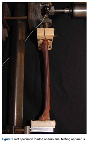
Results
We did not detect a statistical difference in notch depth, notch-to-implant distance, or femoral length between the CR and PS groups. Mean (SD) notch depth was 6.0 (1.3) mm for CR and 4.9 (1.0) mm for PS (P = .13); mean (SD) distance from the proximal end of the notch to the implant was 13.8 (1.7) mm for CR and 11.1 (3.2) mm for PS (P = .08); and mean (SD) femoral length was 46.2 (0.1) cm for CR and 46.2 (0.1) cm for PS (P = .60).
Mean (SD) torsional stiffness for the first 3 precycles was 6.2 (1.2), 8.7 (1.5), and 8.8 (1.4) Nm per degree for the CR group and 6.0 (0.7), 8.4 (1.4), and 8.6 (1.4) Nm per degree for the PS group; the differences were not statistically significant (Figure 2A). In addition, there were no statistically significant differences in mean (SD) stiffness at failure between CR, 6.5 (0.7) Nm per degree, and PS, 7.1 (0.9) Nm per degree (P = .24; Figure 2B) or in mean (SD) final torque at failure between CR, 62.4 (9.4) Nm, and PS, 62.7 (12.2) Nm (P = .95; Figure 2C).
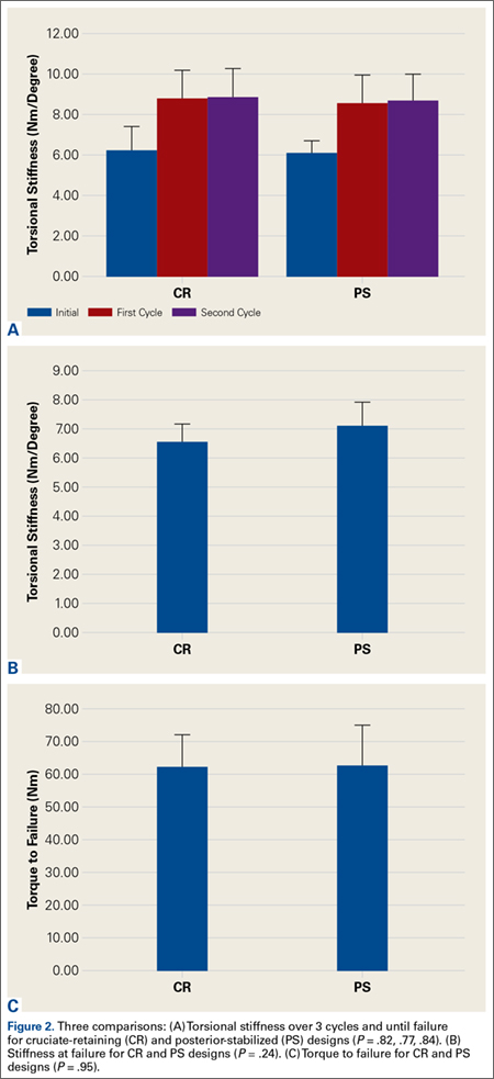
All fractures in both groups were oblique fractures originating at the proximal angle of the notch and extended proximally. None extended distally into the box. Fracture locations and patterns were identical in the CR and PS groups of femurs (Figure 3).
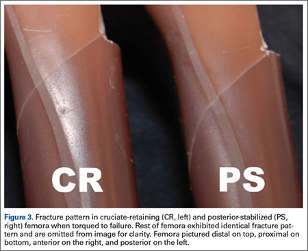
Discussion
Periprosthetic fractures after TKA remain rare. However, these fractures can significantly increase morbidity and complications. Anterior femoral notching occurs inadvertently in 30% to 40% of TKAs.6,17 The impact of femoral notching on supracondylar femur fracture is inconsistent between biomechanical and retrospective clinical studies. Retrospective studies failed to find a significant correlation between anterior femoral notching and supracondylar femur fractures.6,17 However, findings of biomechanical studies have suggested that a notch 3 mm deep will reduce the torsional strength of the femur by 29%.7 Another study, using 3-dimensional finite element analysis, showed a significant increase in local stress with a notch deeper than 3 mm.15
To our knowledge, no clinical studies, including the aforementioned Cochrane review,10 have specifically evaluated the difference in risk for periprosthetic fracture between different TKA models in the presence of notching.11 The biomechanical differences between implant designs could be a confounding factor in the results of past studies. More bone resection is required in PS designs than in CR designs. The position of the PS intercondylar cutout, much lower than the top of the patella flange, should not increase susceptibility to fractures more than in CR designs, but this hypothesis, though accepted, has not been validated biomechanically or addressed specifically in prospective or retrospective clinical analysis. In the present study, we used a biomechanical model to replicate an external rotation failure mechanism and quantify the differences in torsional strength and load to failure between CR TKA and PS TKA models in the presence of anterior femoral notching. Our results showed no significant differences in torsional stiffness, stiffness at failure, or torque at failure between the CR and PS design groups in the presence of anterior femoral notching.
In this study, all femoral fractures were oblique, and they all originated at the site of the cortical defect, not the notch—a situation markedly different from having bending forces applied to the femur. Previous biomechanical data indicated that bending forces applied to a notched femur cause fractures originating at the notch, whereas torsional forces applied to a notched femur cause fractures originating at the anterior aspect of the bone–component interface.7 The difference is attributable to study design. Our femurs were held fixed at their proximal end, which may have exacerbated any bending forces applied during external rotation, but we thought constraining the proximal femur would better replicate a fall involving external rotation.
More important for our study, an oblique fracture pattern was noted for both design groups (CR and PS), indicating the fracture pattern was unrelated to the area from which bone was resected for the PS design. All femur fractures in both design groups occurred proximal to a well-fixed prosthesis, indicating they should be classified as Vancouver C fractures. This is significant because intercondylar fossa resection (PS group) did not convert the fractures into Vancouver B2 fractures, which involve prosthesis loosening caused by pericomponent fracture.18 This simple observation validated our hypothesis that there would be no biomechanical differences between CR and PS designs with respect to the effects of anterior femoral notching. This lack of a significant difference may be attributed to the PS intercondylar cutout being much lower than the top of the anterior flange shielding the resected bone deep to the anterior flange.7 In addition, given the rarity of supracondylar fractures and the lack of sufficient relevant clinical data, it is difficult to speculate on the fracture patterns observed in clinical cases versus biomechanical studies.12
The use of synthetic bone models instead of cadaveric specimens could be seen as a limitation. Although synthetic bones may not reproduce the mechanism of failure in living and cadaveric femurs, the mechanical properties of synthetic bones have previously been found to fall within the range of those of cadaveric bones under axial loading, bending, and torsion testing.13,14 As a uniform testing material, synthetic bones allow removal of the confounding variations in bone size and quality that plague biomechanical studies in cadaveric bones.13,14 Interfemoral variability was 20 to 200 times higher in cadaveric femurs than in synthetic bones, which makes synthetic femurs preferable to cadaveric femurs, especially in studies with a small sample size.13,14 In addition, a uniform specimen provides consistent, reproducible osteotomies, which were crucial for consistent mechanical evaluation of each configuration in this study.
The long-term clinical significance of anterior femoral notching in periprosthetic fractures is equivocal, possibly because most studies predominantly use CR implants.6 This may not be an issue if it is shown that CR and PS implants have the same mechanical properties. Despite the differences between clinical studies and our biomechanical study, reevaluation of clinical data is not warranted given the biomechanical data we present here. Results of biomechanical studies like ours still suggest an increased immediate postoperative risk for supracondylar fracture after anterior cortical notching of the femur.5,7 Ultimately, this study found that, compared with a CR design, a PS design did not alter the torsional biomechanical properties or fracture pattern of an anteriorly notched femur.
1. Culp RW, Schmidt RG, Hanks G, Mak A, Esterhai JL Jr, Heppenstall RB. Supracondylar fracture of the femur following prosthetic knee arthroplasty. Clin Orthop Relat Res. 1987;(222):212-222.
2. Delport PH, Van Audekercke R, Martens M, Mulier JC. Conservative treatment of ipsilateral supracondylar femoral fracture after total knee arthroplasty. J Trauma. 1984;24(9):846-849.
3. Figgie MP, Goldberg VM, Figgie HE 3rd, Sobel M. The results of treatment of supracondylar fracture above total knee arthroplasty. J Arthroplasty. 1990;5(3):267-276.
4. Rorabeck CH, Taylor JW. Periprosthetic fractures of the femur complicating total knee arthroplasty. Orthop Clin North Am. 1999;30(2):265-277.
5. Hirsh DM, Bhalla S, Roffman M. Supracondylar fracture of the femur following total knee replacement. Report of four cases. J Bone Joint Surg Am. 1981;63(1):162-163.
6. Ritter MA, Thong AE, Keating EM, et al. The effect of femoral notching during total knee arthroplasty on the prevalence of postoperative femoral fractures and on clinical outcome. J Bone Joint Surg Am. 2005;87(11):2411-2414.
7. Lesh ML, Schneider DJ, Deol G, Davis B, Jacobs CR, Pellegrini VD Jr. The consequences of anterior femoral notching in total knee arthroplasty. A biomechanical study. J Bone Joint Surg Am. 2000;82(8):1096-1101.
8. Shawen SB, Belmont PJ Jr, Klemme WR, Topoleski LD, Xenos JS, Orchowski JR. Osteoporosis and anterior femoral notching in periprosthetic supracondylar femoral fractures: a biomechanical analysis. J Bone Joint Surg Am. 2003;85(1):115-121.
9. Scuderi GR, Pagnano MW. Review article: the rationale for posterior cruciate substituting total knee arthroplasty. J Orthop Surg (Hong Kong). 2001;9(2):81-88.
10. Verra WC, van den Boom LG, Jacobs W, Clement DJ, Wymenga AA, Nelissen RG. Retention versus sacrifice of the posterior cruciate ligament in total knee arthroplasty for treating osteoarthritis. Cochrane Database Syst Rev. 2013;10:CD004803.
11. Kolisek FR, McGrath MS, Marker DR, et al. Posterior-stabilized versus posterior cruciate ligament-retaining total knee arthroplasty. Iowa Orthop J. 2009;29:23-27.
12. Dennis DA. Periprosthetic fractures following total knee arthroplasty. Instr Course Lect. 2001;50:379-389.
13. Cristofolini L, Viceconti M, Cappello A, Toni A. Mechanical validation of whole bone composite femur models. J Biomech. 1996;29(4):525-535.
14. Heiner AD, Brown TD. Structural properties of a new design of composite replicate femurs and tibias. J Biomech. 2001;34(6):773-781.
15. Beals RK, Tower SS. Periprosthetic fractures of the femur. An analysis of 93 fractures. Clin Orthop Relat Res. 1996;(327):238-246.
16. Gujarathi N, Putti AB, Abboud RJ, MacLean JG, Espley AJ, Kellett CF. Risk of periprosthetic fracture after anterior femoral notching. Acta Orthop. 2009;80(5):553-556.
17. Zalzal P, Backstein D, Gross AE, Papini M. Notching of the anterior femoral cortex during total knee arthroplasty: characteristics that increase local stresses. J Arthroplasty. 2006;21(5):737-743.
18. Gaski GE, Scully SP. In brief: classifications in brief: Vancouver classification of postoperative periprosthetic femur fractures. Clin Orthop Relat Res. 2011;469(5):1507-1510.
Although rare, periprosthetic fractures remain a significant complication after total knee arthroplasty (TKA), occurring in 0.3% to 2.5% of cases.1-4 Hirsh and colleagues5 were among the first to suggest that anterior femoral notching during TKA was a potential risk factor for postoperative periprosthetic femoral fracture because notching may weaken the anterior femoral cortex. Anterior femoral notching, a cortex violation occurring during an anterior bone cut, occurs in up to 30% of cases.6 Using a theoretical biomechanical model, Culp and colleagues1 found that increasing the depth of the notch defect into the cortex led to reduced torsional strength. In more recent, cadaveric biomechanical studies, notching of the anterior femoral cortex decreased torsional strength by up to 39%.7,8 Contrary to these biomechanical studies, a retrospective study evaluating 1089 TKAs using 2 implant designs (Anatomic Graduated Component, Biomet and Legacy, Zimmer) demonstrated no significant effect of anterior femoral notching with respect to incidence of supracondylar femur fractures.6 That study, however, did not address whether implant design is associated with a differential risk for fracture in the presence of anterior notching.
Previous biomechanical studies have primarily investigated cruciate-retaining (CR) femoral components and properties with respect to anterior notching, even though the posterior-stabilized (PS) design is used more often in the United States.1,7 According to a Mayo Clinic survey, TKAs with a PS design increased from <10% in 1990 to almost 75% by 1997.9 Today, there is little to no consensus about which implant is better, and use of one or the other depends largely on the surgeon and varies widely between countries and regions.10 PS designs require more bone resection and demonstrate prosthesis-controlled rollback during flexion, whereas CR designs preserve more bone and achieve posterior stabilization via the posterior cruciate ligament.11 Despite these differences in design and mechanics, a 2013 Cochrane review of TKA design found no clinically significant differences between CR and PS with respect to pain, range of motion, or clinical and radiologic outcomes.10 The reviewers did not specifically address periprosthetic fractures associated with either femoral notching or TKA design, as they could not quantitatively analyze postoperative complications because of the diversity of reports. Given the limited number of reported cases, a review of radiographic findings pertaining to the characteristics of supracondylar fractures in anterior femoral notching was unsuccessful.12 As the previous biomechanical studies of anterior notching used primarily CR models or no prostheses at all, a study of biomechanical differences between CR and PS designs in the presence of anterior notching is warranted.1,7,8 Therefore, we conducted a study to assess the effect of anterior femoral notching on torsional strength and load to failure in CR and PS femoral components.
Materials and Methods
Twelve fourth-generation composite adult left femur synthetic sawbones (Sawbones; Pacific Research Laboratories) were selected for their consistent biomechanical properties, vs those of cadaveric specimens; in addition, low intersample variability made them preferable to cadaveric bones given the small sample used in this study.13,14 All bones were from the same lot. All were visually inspected for defects and found to be acceptable. In each sample, an anterior cortical defect was created by making an anterior cut with an undersized (size 4) posterior referencing guide. In addition, the distance from the proximal end of the notch to the implant fell within 15 mm, as that is the maximum distance from the implant a notch can be placed using a standard femoral cutting jig.15 Six femora were instrumented with CR implants and 6 with PS implants (DePuy Synthes). Implants were placed using standardized cuts. Before testing, each implant was inspected for proper fit and found to be securely fastened to the femur. In addition, precision calipers were used to measure notch depth and distance from notch to implant before loading. A custom polymethylmethacrylate torsion jig was used to fix each instrumented femur proximally and distally on the femoral implant (Figure 1). Care was taken to ensure the distal jig engaged only the implant, thus isolating the notch as a stress riser. Each femur was loaded in external rotation through the proximal femoral jig along the anatomical axis. Use of external rotation was based on study findings implicating external rotation of the tibia as the most likely mechanism for generating a fracture in the event of a fall.12 Furthermore, distal femur fractures are predominantly spiral as opposed to butterfly or bending—an indication that torsion is the most likely mechanism of failure.16 With no axial rotation possible within the prosthesis, increased torsional stress is undoubtedly generated within adjacent bone. Each specimen underwent torsional stiffness testing and then load to failure. Torsional stiffness was measured by slowly loading each femur in external rotation, from 1 to 18 Nm for 3 cycles at a displacement rate of 0.5° per second. Each specimen then underwent torsional load-to-failure testing on an Instron 5800R machine at a rate of 0.5° per second. Failure was defined as the moment of fracture and subsequent decrease in torsional load—determined graphically by the peak torsional load followed immediately by a sharp decrease in load. Stiffness was determined as the slope of torque to the displacement curve for each cycle, and torque to failure was the highest recorded torque before fracture. Fracture pattern was noted after failure. A sample size of 6 specimens per group provided 80% power to detect a between-group difference of 1 Nm per degree in stiffness, using an estimated SD of 0.7 Nm per degree. In our statistical analysis, continuous variables are reported as means and SDs. Data from our torsional stiffness and load-to-failure testing were analyzed with unpaired 2-sample t tests, and P < .05 was considered statistically significant.
Results
We did not detect a statistical difference in notch depth, notch-to-implant distance, or femoral length between the CR and PS groups. Mean (SD) notch depth was 6.0 (1.3) mm for CR and 4.9 (1.0) mm for PS (P = .13); mean (SD) distance from the proximal end of the notch to the implant was 13.8 (1.7) mm for CR and 11.1 (3.2) mm for PS (P = .08); and mean (SD) femoral length was 46.2 (0.1) cm for CR and 46.2 (0.1) cm for PS (P = .60).
Mean (SD) torsional stiffness for the first 3 precycles was 6.2 (1.2), 8.7 (1.5), and 8.8 (1.4) Nm per degree for the CR group and 6.0 (0.7), 8.4 (1.4), and 8.6 (1.4) Nm per degree for the PS group; the differences were not statistically significant (Figure 2A). In addition, there were no statistically significant differences in mean (SD) stiffness at failure between CR, 6.5 (0.7) Nm per degree, and PS, 7.1 (0.9) Nm per degree (P = .24; Figure 2B) or in mean (SD) final torque at failure between CR, 62.4 (9.4) Nm, and PS, 62.7 (12.2) Nm (P = .95; Figure 2C).
All fractures in both groups were oblique fractures originating at the proximal angle of the notch and extended proximally. None extended distally into the box. Fracture locations and patterns were identical in the CR and PS groups of femurs (Figure 3).
Discussion
Periprosthetic fractures after TKA remain rare. However, these fractures can significantly increase morbidity and complications. Anterior femoral notching occurs inadvertently in 30% to 40% of TKAs.6,17 The impact of femoral notching on supracondylar femur fracture is inconsistent between biomechanical and retrospective clinical studies. Retrospective studies failed to find a significant correlation between anterior femoral notching and supracondylar femur fractures.6,17 However, findings of biomechanical studies have suggested that a notch 3 mm deep will reduce the torsional strength of the femur by 29%.7 Another study, using 3-dimensional finite element analysis, showed a significant increase in local stress with a notch deeper than 3 mm.15
To our knowledge, no clinical studies, including the aforementioned Cochrane review,10 have specifically evaluated the difference in risk for periprosthetic fracture between different TKA models in the presence of notching.11 The biomechanical differences between implant designs could be a confounding factor in the results of past studies. More bone resection is required in PS designs than in CR designs. The position of the PS intercondylar cutout, much lower than the top of the patella flange, should not increase susceptibility to fractures more than in CR designs, but this hypothesis, though accepted, has not been validated biomechanically or addressed specifically in prospective or retrospective clinical analysis. In the present study, we used a biomechanical model to replicate an external rotation failure mechanism and quantify the differences in torsional strength and load to failure between CR TKA and PS TKA models in the presence of anterior femoral notching. Our results showed no significant differences in torsional stiffness, stiffness at failure, or torque at failure between the CR and PS design groups in the presence of anterior femoral notching.
In this study, all femoral fractures were oblique, and they all originated at the site of the cortical defect, not the notch—a situation markedly different from having bending forces applied to the femur. Previous biomechanical data indicated that bending forces applied to a notched femur cause fractures originating at the notch, whereas torsional forces applied to a notched femur cause fractures originating at the anterior aspect of the bone–component interface.7 The difference is attributable to study design. Our femurs were held fixed at their proximal end, which may have exacerbated any bending forces applied during external rotation, but we thought constraining the proximal femur would better replicate a fall involving external rotation.
More important for our study, an oblique fracture pattern was noted for both design groups (CR and PS), indicating the fracture pattern was unrelated to the area from which bone was resected for the PS design. All femur fractures in both design groups occurred proximal to a well-fixed prosthesis, indicating they should be classified as Vancouver C fractures. This is significant because intercondylar fossa resection (PS group) did not convert the fractures into Vancouver B2 fractures, which involve prosthesis loosening caused by pericomponent fracture.18 This simple observation validated our hypothesis that there would be no biomechanical differences between CR and PS designs with respect to the effects of anterior femoral notching. This lack of a significant difference may be attributed to the PS intercondylar cutout being much lower than the top of the anterior flange shielding the resected bone deep to the anterior flange.7 In addition, given the rarity of supracondylar fractures and the lack of sufficient relevant clinical data, it is difficult to speculate on the fracture patterns observed in clinical cases versus biomechanical studies.12
The use of synthetic bone models instead of cadaveric specimens could be seen as a limitation. Although synthetic bones may not reproduce the mechanism of failure in living and cadaveric femurs, the mechanical properties of synthetic bones have previously been found to fall within the range of those of cadaveric bones under axial loading, bending, and torsion testing.13,14 As a uniform testing material, synthetic bones allow removal of the confounding variations in bone size and quality that plague biomechanical studies in cadaveric bones.13,14 Interfemoral variability was 20 to 200 times higher in cadaveric femurs than in synthetic bones, which makes synthetic femurs preferable to cadaveric femurs, especially in studies with a small sample size.13,14 In addition, a uniform specimen provides consistent, reproducible osteotomies, which were crucial for consistent mechanical evaluation of each configuration in this study.
The long-term clinical significance of anterior femoral notching in periprosthetic fractures is equivocal, possibly because most studies predominantly use CR implants.6 This may not be an issue if it is shown that CR and PS implants have the same mechanical properties. Despite the differences between clinical studies and our biomechanical study, reevaluation of clinical data is not warranted given the biomechanical data we present here. Results of biomechanical studies like ours still suggest an increased immediate postoperative risk for supracondylar fracture after anterior cortical notching of the femur.5,7 Ultimately, this study found that, compared with a CR design, a PS design did not alter the torsional biomechanical properties or fracture pattern of an anteriorly notched femur.
1. Culp RW, Schmidt RG, Hanks G, Mak A, Esterhai JL Jr, Heppenstall RB. Supracondylar fracture of the femur following prosthetic knee arthroplasty. Clin Orthop Relat Res. 1987;(222):212-222.
2. Delport PH, Van Audekercke R, Martens M, Mulier JC. Conservative treatment of ipsilateral supracondylar femoral fracture after total knee arthroplasty. J Trauma. 1984;24(9):846-849.
3. Figgie MP, Goldberg VM, Figgie HE 3rd, Sobel M. The results of treatment of supracondylar fracture above total knee arthroplasty. J Arthroplasty. 1990;5(3):267-276.
4. Rorabeck CH, Taylor JW. Periprosthetic fractures of the femur complicating total knee arthroplasty. Orthop Clin North Am. 1999;30(2):265-277.
5. Hirsh DM, Bhalla S, Roffman M. Supracondylar fracture of the femur following total knee replacement. Report of four cases. J Bone Joint Surg Am. 1981;63(1):162-163.
6. Ritter MA, Thong AE, Keating EM, et al. The effect of femoral notching during total knee arthroplasty on the prevalence of postoperative femoral fractures and on clinical outcome. J Bone Joint Surg Am. 2005;87(11):2411-2414.
7. Lesh ML, Schneider DJ, Deol G, Davis B, Jacobs CR, Pellegrini VD Jr. The consequences of anterior femoral notching in total knee arthroplasty. A biomechanical study. J Bone Joint Surg Am. 2000;82(8):1096-1101.
8. Shawen SB, Belmont PJ Jr, Klemme WR, Topoleski LD, Xenos JS, Orchowski JR. Osteoporosis and anterior femoral notching in periprosthetic supracondylar femoral fractures: a biomechanical analysis. J Bone Joint Surg Am. 2003;85(1):115-121.
9. Scuderi GR, Pagnano MW. Review article: the rationale for posterior cruciate substituting total knee arthroplasty. J Orthop Surg (Hong Kong). 2001;9(2):81-88.
10. Verra WC, van den Boom LG, Jacobs W, Clement DJ, Wymenga AA, Nelissen RG. Retention versus sacrifice of the posterior cruciate ligament in total knee arthroplasty for treating osteoarthritis. Cochrane Database Syst Rev. 2013;10:CD004803.
11. Kolisek FR, McGrath MS, Marker DR, et al. Posterior-stabilized versus posterior cruciate ligament-retaining total knee arthroplasty. Iowa Orthop J. 2009;29:23-27.
12. Dennis DA. Periprosthetic fractures following total knee arthroplasty. Instr Course Lect. 2001;50:379-389.
13. Cristofolini L, Viceconti M, Cappello A, Toni A. Mechanical validation of whole bone composite femur models. J Biomech. 1996;29(4):525-535.
14. Heiner AD, Brown TD. Structural properties of a new design of composite replicate femurs and tibias. J Biomech. 2001;34(6):773-781.
15. Beals RK, Tower SS. Periprosthetic fractures of the femur. An analysis of 93 fractures. Clin Orthop Relat Res. 1996;(327):238-246.
16. Gujarathi N, Putti AB, Abboud RJ, MacLean JG, Espley AJ, Kellett CF. Risk of periprosthetic fracture after anterior femoral notching. Acta Orthop. 2009;80(5):553-556.
17. Zalzal P, Backstein D, Gross AE, Papini M. Notching of the anterior femoral cortex during total knee arthroplasty: characteristics that increase local stresses. J Arthroplasty. 2006;21(5):737-743.
18. Gaski GE, Scully SP. In brief: classifications in brief: Vancouver classification of postoperative periprosthetic femur fractures. Clin Orthop Relat Res. 2011;469(5):1507-1510.
Clinical and Sonographic Evaluation of Bicortical Button for Proximal Biceps Tenodesis
The long head of the biceps (LHB) tendon is a recognized source of shoulder pain. LHB tendon pathology is commonly associated with other shoulder conditions, such as superior labral tears, rotator cuff tears, or subacromial impingement, whereas isolated pathology, such as traumatic ruptures, tendinosis, or medial subluxation, is rare.1 Treatment of LHB pathology ranges from conservative measures to surgical measures, including tenotomy or tenodesis.2 LHB tenodesis offers the advantage of maintaining the length–tension relationship of the biceps muscle to prevent atrophy and avoid the Popeye deformity incurred from tenotomy alone. Tenodesis also prevents muscle cramping associated with contracted biceps muscle and better maintains elbow flexion and supination strength, which may be decreased with tenotomy.3 In addition, when a subpectoral biceps tenodesis technique is used, pain from LHB tendinopathy in the intertubercular groove may be reduced.4
Open subpectoral biceps tenodesis is a reproducible, efficient method for LHB tenodesis.4,5 A variety of fixation devices has been used: bone tunnels,6 keyhole fixation,7 suture anchors,6-9 and interference screws.6-8,10,11 More recently, a bicortical button has been used for LHB tendon tenodesis.12 Biomechanical studies have shown that load to failure is comparable for bicortical button fixation and interference screw fixation.13,14 In other models of tendon repair, the bicortical button has strength and stability comparable to those of interference screw fixation and enables earlier rehabilitation.15-17 However, there is concern that bicortical button fixation may result in axillary nerve (AN) or posterior circumflex humeral artery (PCHA) compromise because of the proximity of these neurovascular structures to the bicortical button.13,18-21
We conducted a study to functionally and sonographically assess the outcomes of patients who underwent open subpectoral biceps tenodesis with a bicortical button. Functional outcomes were assessed with patient-reported outcomes and physician-reported outcomes. Sonographic studies were used to evaluate the integrity of the tenodesis and determine the proximity of the button to the AN and the PCHA along the posterior proximal humerus.
Methods
After obtaining Institutional Review Board approval for this study, we retrospectively identified 28 consecutive patients who had proximal biceps tenodesis performed by a single surgeon (Dr. K.E. Swanson) using a mini-open subpectoral biceps tenodesis technique with a bicortical button between March 2011 and January 2013. All 28 patients were asked to participate in the study. Twenty-four (86%) agreed to complete 2 surgical outcome surveys, and 18 (64%) completed a 3-part clinical examination at minimum 12-month follow-up.
One of the surveys was Quick Disabilities of the Arm, Shoulder, and Hand (QuickDASH), a validated comprehensive disability survey that scores upper extremity functionality on a scale ranging from 0 (none) to 100 (extreme difficulty).22,23 The other survey scored pain on a scale ranging from 0 (none) to 100 (worst pain).
The clinical examination was completed during a single visit by an orthopedic surgeon (Dr. Meadows or Dr. Diesselhorst) different from the primary surgeon (Dr. K.E. Swanson) and by a clinician-sonologist (Dr. Finnoff). The examination’s 3 parts were physical examination of arm, biceps supination strength test, and ultrasonographic evaluation.
Physical Examination of Arm. Physical examination included palpation of bicipital groove, range of motion (ROM) of shoulder and elbow, and clinical deformity of biceps. Patients were questioned regarding symptoms of AN damage, including sensory and motor findings. Bicipital groove tenderness was assessed with a visual analog scale rating pain 0 to 10. ROM was measured in degrees and was presented as a percentage of full elbow ROM (150°) and full shoulder ROM (180°).
Biceps Supination Strength Test. Biceps supination strength was tested with a baseline hydraulic wrist dynamometer with door handle attachment. Patients were seated with the elbow bent 90° and the forearm in a neutral position. In a series of 3 trials, the patient maintained grip of the dynamometer doorknob while supinating the forearm. The tenodesed (operated) arm and contralateral unaffected (nonoperated) arm were tested in random order and recorded in pounds.
Ultrasonographic Evaluation. Ultrasonography was used to evaluate the tenodesis site. In each case, the biceps tendon was assessed to determine the location of the bicortical button in relation to the AN/PCHA neurovascular bundle. Whereas nerves are difficult to visualize with ultrasonography, arteries are readily seen. Dr. Finnoff used a CX50 ultrasound machine (Philips Medical Systems) with either a 12-3 MHz linear array or a 5-1 MHz curvilinear array transducer to measure the shortest distance from the PCHA to the button.
Each patient was placed in a lateral decubitus or prone position, and the skin of the upper arm was exposed. Tendon integrity was deemed either intact (continuity between biceps tendon and cortical button) or disrupted (lack of continuity between tendon and cortical button). The transducer was then placed in an anatomical sagittal plane over the posterior aspect of the proximal humerus. Power Doppler and cephalad and caudad transducer glides were used to identify the location of the PCHA. The transducer was then glided laterally and anteriorly around the humerus, following the course of the PCHA, until the cortical button was located. The narrowest interval between the PCHA and the cortical button was measured using the ultrasound machine’s software. A still image of each measurement was saved.
Surgical Technique
Biceps tenodesis indications included high-demand heavy laborers, athletes, and patients who preferred the cosmetic results of tenodesis over tenotomy. Most patients had acute symptomatic tears of the superior labrum with instability of the biceps anchor complex. Others had fraying and tenosynovitis of the LHB tendon. Any associated pathology was addressed during the same surgical period.
The surgical technique used was similar to that described by Snir and colleagues.12 Each patient was placed in the lateral decubitus position. Once pathology confirmed biceps tenodesis, the biceps tendon was tenotomized at the base of the superior labrum. A 3-cm incision was made along the axillary fold centered over the inferior border of the pectoralis major tendon. Blunt dissection was performed to define the inferior border of the pectoralis major tendon and to palpate the underlying biceps tendon as it exited the intertubercular groove. The LHB tendon was removed and prepared with No. 2 Fiberwire (Arthrex) in Krackow fashion starting 2 cm proximal to the musculotendinous junction. The excess tendon was excised.
A 3.2-mm guide wire was centered along the most distal aspect of the biceps groove and then drilled through the anterior cortex and just through the posterior cortex. A cannulated reamer, selected on the basis of the biceps tendon diameter (typically, 5-7 mm), was then drilled over the guide wire through the anterior cortex only. The Food and Drug Administration–approved cortical button (BicepsButton; Arthrex) was then loaded by passing the tendon suture ends through each side of the button in alternating fashion, thus allowing the button to slide along the sutures.
The button was loaded onto the BicepsButton deployment device and inserted through the drilled tunnel of the anterior cortex and just through the posterior cortex. The deployment device was then removed, and 1 suture end was pulled to allow the button to engage the posterior humeral cortex. Pulling on both sutures allowed the biceps tendon to slide through the anterior cortex hole of the humerus until the tendon reached the posterior humeral cortex. Tension was verified, and the sutures were tied over the tendon. The wound was then irrigated and closed.
Rehabilitation Program
Patients completed a standard rehabilitation protocol for biceps tenodesis24 along with rehabilitation protocols for any additional procedures performed. In phase 1 (weeks 0-2), they focused on gradual restoration of passive ROM and remained in a sling. In phase 2 (weeks 2-6), they focused on gradual restoration of active ROM, and by week 3 were weaned out of the sling. In phase 3 (weeks 6-8), they continued ROM and strengthening exercises to normalize strength, endurance, and neuromuscular control. In phase 4 (weeks 8-12), they focused on advanced strengthening exercises and return to activities.
Statistical Analysis
Descriptive statistics included means, medians, and SDs. Comparisons between operated and nonoperated arms and between dominant and nondominant arms were performed by a statistician using paired t tests with P = .05. Confidence intervals were calculated for operated and nonoperated arms and for dominant and nondominant arms by using the differences between them.
Results
Functional Outcomes
Surgical outcome scores and pain scores were obtained from 24 patients (86%) at minimum 12-month follow-up. Mean (SD) DASH score was 15.15 (17.6; median, 9), and mean (median) pain score was 12.61 (7).
Eighteen patients (64%) completed the clinical examination: 16 men (88.9%) and 2 women (11.1%). Mean age was 48.3 years (age range, 33-59 years). Of these 18 patients, 9 (50%) had surgery on the dominant arm, and the other 9 had surgery on the nondominant arm. All patients were right-hand–dominant. In 3 patients, biceps tenodesis was performed with only minimal arthroscopic débridement (20%); in the other 15, biceps tenodesis was performed concomitantly with 1 or more additional arthroscopic procedures: acromioplasty (73%), rotator cuff repair (47%), distal clavicle resection (33%), subacromial bursectomy (13%), microfracture of glenoid (13%), and posterior labral repair (7%).
The clinical examination was performed a mean of 15.2 months (range, 12-26 months) after surgery. Physical examination findings are listed in Table 1.
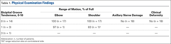
Forearm supination strength, averaged from 3 trials on each arm, was significantly (P = .01) greater in the nonoperated arm than in the operated arm (Table 2, Figure 1). A 95% confidence interval for the mean (SD) difference in strength was 9.35 (7.76) pounds, meaning that on average, the nonoperated arm will be 1.59 to 17.11 pounds stronger than the operated arm. In addition, strength of the dominant arm was greater than that of the nondominant arm (P = .05) regardless of which arm underwent surgery (Table 2, Figure 1). However, the mean (SD) difference in strength was 6.94 (8.39) pounds, indicating the observed difference was not statistically significant.
![]()
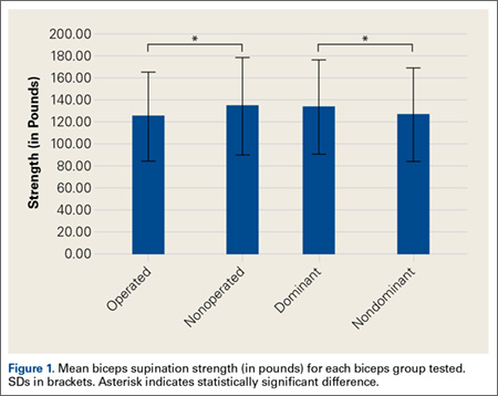
Sonographic Evaluation
According to the sonographic evaluations, the tenodesis was intact in all 18 patients (Figure 2). Estimated mean (SD) distance from button to PCHA was 18.17 (9.0) mm (median, 16.1 mm; range, 9.4-48 mm) (Figure 2, Figure 3). No patient indicated any symptoms of AN damage.

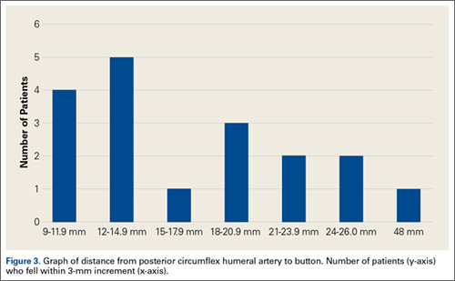
Discussion
There are few studies of functional outcomes of biceps tenodesis. Pain is a common measure of patient satisfaction. Mazzocca and colleagues25 reported a mean follow-up pain score of 1.1 (range, 0.5-1.9) out of 10 for a group of 41 patients who had subpectoral tenodesis with an interference screw. Millett and colleagues26 reported a mean postoperative pain score of 2.5 out of 10 for patients who had subpectoral interference screw fixation. Our patients reported a mean pain score of 12.6 out of 100 after minimum 12-month follow-up. We also assessed for pain in the intertubercular groove during palpation. Although some studies have shown that groove pain was eliminated by subpectoral biceps tenodesis,5 3 patients in our study had pain on groove palpation. The cause of this residual pain is unclear, but some studies have suggested a chronic degenerative pathologic process that occurs while the tendon is within the biceps groove.27 Removing the tendon from the groove may not remove the underlying cause of pain.
Our patients’ mean DASH score was 15.15 (within the excellent range). Normative mean (SD) DASH score for the general population is 10.1 (14.68).28
Functional strength of forearm supination, shoulder ROM, and elbow ROM are objective measures of patient performance after fixation. On Cybex testing, Phillips and colleagues29 found no difference in forearm supination strength or elbow flexion (compared with contralateral arm) after biceps tenodesis or conservative treatment for proximal biceps ruptures. Shank and colleagues30 compared elbow flexion and supination strength of the affected and unaffected arms after suture anchor subpectoral biceps tenodesis. There was no significant difference in Cybex results, but there was a 14% to 15% loss of average strength in the tenodesed versus nonsurgical arm. In the present study, we found a significant difference in forearm supination strength between the operated and nonoperated arms, but with only a 7% loss of average strength in the operated arms. The difference in strength ranged from 1.59 to 17.11 pounds, which may not be clinically significant, as supination strength ranged from 60 to 270 pounds.
Of the 18 patients in this study, 9 had surgery on the dominant arm, and the other 9 had surgery on the nondominant arm. Examining the effect of arm dominance on results revealed that patients with surgery on the nondominant arm tended to have substantially reduced supination strength in that arm vs the dominant arm. There was an 11% loss of average strength for nondominant vs dominant arms that had surgery. Examining nondominant arms only revealed a 13% loss of strength for operated vs nonoperated arms. There was no difference in forearm supination strengths between nonoperated arms (dominant vs nondominant) or between dominant arms (operated vs nonoperated). This suggests that, though hand dominance may not play a significant role in control patients’ forearm supination strength,30 it may have a substantial effect on surgical patients’ ability to regain strength when the nondominant arm is the surgical arm. One objective of this study was to measure the distance between the biceps cortical button on the posterior humeral cortex and the AN/PCHA neurovascular bundle. The AN bundles with the PCHA posterior to the humeral neck.31-33 As the AN travels with the PCHA, and the PCHA has been reliably identified with Doppler ultrasonography,34-36 the PCHA was used as a marker for the AN in this study. Our bicortical button technique places the button on the posterior aspect of the humerus, making AN and PCHA the nearest at-risk neurovascular structures. None of our patients had symptoms of AN damage. However, 2 patients indicated pain in the posterior aspect of the humerus during deltoid activation. Distance from the neurovascular structures to the button was 48 mm in one patient and 13.6 mm in the other. DASH scores were 43 and 27, respectively. Both patients’ 1-year pain score was 30. The first patient underwent arthroscopic acromioplasty, distal clavicle resection, and microfracture of the glenoid surface in addition to the subpectoral biceps tenodesis; the second underwent subacromial decompression and distal clavicle resection in addition to the subpectoral biceps tenodesis. Whether the associated pathology contributed to their persistent pain is unknown. However, given the distance from AN/PCHA to button, it is unlikely that their pain was a result of neurovascular compromise from the procedure.
Advantages of the cortical button include the ability to drill a smaller hole in the humerus for fixation, compared with the hole drilled for an interference screw. Despite the biomechanical strength of the screw, large (8 mm) cortical violations have been associated with increased fracture risk of the proximal humerus.37,38 The tendon may experience less trauma than that caused by being twisted against an interference screw, the most common location of failure of which is the tendon–screw interface.39 In addition, tendon healing may be improved through circumferential healing in the cortical button tunnel.
A concern of using a bicortical button for fixation is drilling through the posterior cortex, because of the proximity of the posterior neurovascular structures. In a case in which the posterior cord was injured, Rhee and colleagues40 used a suture pullout technique whereby a Beath pin was passed out of the posterior humerus and soft tissues to then hold tension on the biceps tendon during the tenodesis. The radial nerve potentially could have been injured by pin overpenetration or by becoming wrapped up in the soft tissues as the pin was spinning through them. In our technique, the posterior humeral cortex is drilled cautiously to avoid overpenetration and possibly getting the posterior soft tissues wrapped up in the guide pin. No AN injuries have been reported with this technique. Mean distance from AN to posterior cortical button in this study was 18.17 mm. In 2 cadaver studies of bicortical drilling for subpectoral biceps tenodesis, the ANs were 25.1 mm and 36.7 mm from the posterior drill hole.41,21
Limitations of this study included its design (case series) and limited number of follow-up patients. Of the 28 consecutive patients identified for the study, 10 did not undergo the clinical examination, as they either lived more than 3 hours away (8 patients) or could not be contacted (2 patients). Another study limitation was the inability to directly image ANs with ultrasound. Therefore, measurements of the distance from the PCHA to the button were used to estimate the distance from the AN/PCHA neurovascular bundle to the button.
In this study, functional outcomes were excellent, and there were no tenodesis failures or neurovascular complications. These preliminary findings indicate that subpectoral biceps tenodesis with a bicortical button is a viable treatment option for patients with the appropriate indications for this procedure.
1. Khazzam M, George MS, Churchill RS, Kuhn JE. Disorders of the long head of biceps tendon. J Shoulder Elbow Surg. 2012;21(1):136-145.
2. Geaney LE, Mazzocca AD. Biceps brachii tendon ruptures: a review of diagnosis and treatment of proximal and distal biceps tendon ruptures. Phys Sportsmed. 2010;38(2):117-125.
3. Kelly AM, Drakos MC, Fealy S, Taylor SA, O’Brien SJ. Arthroscopic release of the long head of the biceps tendon: functional outcome and clinical results. Am J Sports Med. 2005;33(2):208-213.
4. Provencher MT, LeClere LE, Romeo AA. Subpectoral biceps tenodesis. Sports Med Arthrosc Rev. 2008;16(3):170-176.
5. Nho SJ, Reiff SN, Verma NN, Slabaugh MA, Mazzocca AD, Romeo AA. Complications associated with subpectoral biceps tenodesis: low rates of incidence following surgery. J Shoulder Elbow Surg. 2010;19(5):764-768.
6. Mazzocca AD, Bicos J, Santangelo S, Romeo AA, Arciero RA. The biomechanical evaluation of four fixation techniques for proximal biceps tenodesis. Arthroscopy. 2005;21(11):1296-1306.
7. Ozalay, M, Akpinar S, Karaeminogullari O, et al. Mechanical strength of four different biceps tenodesis techniques. Arthroscopy. 2005;21(8):992-998.
8. Golish RS, Caldwell PE, Miller MD, et al. Interference screw versus suture anchor fixation for subpectoral tenodesis of the proximal biceps tendon: a cadaveric study. Arthroscopy. 2008;24(10):1103-1108.
9. Richards DP, Burkhart SS. A biomechanical analysis of two biceps tenodesis fixation techniques. Arthroscopy. 2005;21(7):861-866.
10. Mazzocca AD, Rios CG, Romeo AA, Arciero RA. Subpectoral biceps tenodesis with interference screw fixation. Arthroscopy. 2005;21(7):896.
11. Wolf RS, Zheng N, Weichel D. Long head biceps tenotomy versus tenodesis: a cadaveric biomechanical analysis. Arthroscopy. 2005;21(2):182-185.
12. Snir N, Hamula M, Wolfson T, Laible C, Sherman O. Long head of the biceps tenodesis with cortical button technique. Arthrosc Tech. 2013;2(2):e95-e97.
13. Arora AS, Singh A, Koonce RC. Biomechanical evaluation of a unicortical button versus interference screw for subpectoral biceps tenodesis. Arthroscopy. 2013;29(4):638-644.
14. Buchholz A, Martetschläger F, Siebenlist S, et al. Biomechanical comparison of intramedullary cortical button fixation and interference screw technique for subpectoral biceps tenodesis. Arthroscopy. 2013;29(5):845-853.
15. Bain GI, Prem H, Heptinstall RJ, Verhellen R, Paix D. Repair of distal biceps tendon rupture: a new technique using the Endobutton. J Shoulder Elbow Surg. 2000;9(2):120-126.
16. Greenberg JA. Endobutton repair of distal biceps tendon ruptures. J Hand Surg Am. 2009;34(8):1541-1548.
17. Heinzelmann AD, Savoie FH 3rd, Ramsey JR, Field LD, Mazzocca AD. A combined technique for distal biceps repair using a soft tissue button and biotenodesis interference screw. Am J Sports Med. 2009;37(5):989-994.
18. DeAngelis JP, Chen A, Wexler M, et al. Biomechanical characterization of unicortical button fixation: a novel technique for proximal subpectoral biceps tenodesis. Knee Surg Sports Traumatol Arthrosc. 2015;23(5):1434-1441.
19. Dickens JF, Kilcoyne KG, Tintle SM, Giuliani J, Schaefer RA, Rue JP. Subpectoral biceps tenodesis: an anatomic study and evaluation of at-risk structures. Am J Sports Med. 2012;40(10):2337-2341.
20. Sethi PM, Rajaram A, Beitzel K, Hackett TR, Chowaniec DM, Mazzocca AD. Biomechanical performance of subpectoral biceps tenodesis: a comparison of interference screw fixation, cortical button fixation, and interference screw diameter. J Shoulder Elbow Surg. 2013;22(4):451-457.
21. Sethi PM, Vadasdi K, Greene RT, Vitale MA, Duong M, Miller SR. Safety of open suprapectoral and subpectoral biceps tenodesis: an anatomic assessment of risk for neurologic injury. J Shoulder Elbow Surg. 2015;24(1):138-142.
22. Gummesson C, Ward MM, Atroshi I. The shortened Disabilities of the Arm, Shoulder and Hand questionnaire (QuickDASH): validity and reliability based on responses within the full-length DASH. BMC Musculoskelet Disord. 2006;7:44.
23. Schmidt CC, Brown BT, Sawardeker PJ, DeGravelle M Jr, Miller MC. Factors affecting supination strength after a distal biceps rupture. J Shoulder Elbow Surg. 2014;23(1):68-75.
24. Brotzman SB, Wilk KE, eds. Handbook of Orthopaedic Rehabilitation. Philadelphia, PA: Mosby Elsevier; 2007.
25. Mazzocca AD, Cote MP, Arciero CL, Romeo AA, Arciero RA. Clinical outcomes after subpectoral biceps tenodesis with an interference screw. Am J Sports Med. 2008;36(10):1922-1929.
26. Millett PJ, Snaders B, Gobezie R, Braun S, Warner JP. Interference screw versus suture anchor fixation for open subpectoral biceps tenodesis: does it matter? BMC Musculoskelet Disord. 2008;9(121):1-6.
27. Streit JJ, Shishani Y, Rodgers M, Gobezie R. Tendinopathy of the long head of the biceps tendon: histopathologic analysis of the extra-articular biceps tendon and tenosynovium. Open Access J Sports Med. 2015;6:63-70.
28. Hunsaker FG, Cioffi DA, Amadio PC, Wright JG, Caughlin B. The American Academy of Orthopaedic Surgeons outcomes instruments: normative values from the general population. J Bone Joint Surg Am. 2002;84(2):208-215.
29. Phillips BB, Canale ST, Sisk TD, Stralka SW, Wyatt KP. Rupture of the proximal biceps tendon in middle-aged patients. Orthop Rev. 1993;22(3):349-353.
30. Shank JR, Singleton SB, Braun S, et al. A comparison of forearm supination and elbow flexion strength in patients with long head of the biceps tenotomy or tenodesis. Arthroscopy. 2011;27(1):9-16.
31. Apaydin N, Tubbs RS, Loukas M, Duparc F. Review of the surgical anatomy of the axillary nerve and the anatomic basis of its iatrogenic and traumatic injury. Surg Radiol Anat. 2010;32(3):193-201.
32. Johnson D. Pectoral girdle and upper limp. In: Standring S, ed. Gray’s Anatomy. 40th ed. New York, NY: Elsevier; 2008:814-821.
33. Tubbs RS, Tyler-Kabara EC, Aikens AC, et al. Surgical anatomy of the axillary nerve within the quadrangular space. J Neurosurg. 2005;102(5):912-914.
34. Kim YA, Yoon KB, Kwon TD, Kim DH, Yoon DM. Evaluation of anatomic landmarks for axillary nerve block in the quadrilateral space. Acta Anaesthesiol Scand. 2014;58(5):567-571.
35. Robinson DJ, Marks P, Schneider-Kolsky ME. Ultrasound of the posterior circumflex humeral artery. J Med Imaging Radiat Oncol. 2010;54(3):219-223.
36. Rothe C, Asghar S, Andersen HL, Christensen JK, Lange KH. Ultrasound-guided block of the axillary nerve: a volunteer study of a new method. Acta Anaesthesiol Scand. 2011;55(5):565-570.
37. Reiff SN, Nho SJ, Romeo AA. Proximal humerus fracture after keyhole biceps tenodesis. Am J Orthop. 2010;39(7):E61-E63.
38. Sears BW, Spencer EE, Getz CL. Humeral fracture following subpectoral biceps tenodesis in 2 active, healthy patients. J Shoulder Elbow Surg. 2011;20(6):e7-e11.
39. Koch BS, Burks RT. Failure of biceps tenodesis with interference screw fixation. Arthroscopy. 2012;28(5):735-740.
40. Rhee PC, Spinner RJ, Bishop AT, Shin AY. Iatrogenic brachial plexus injuries associated with open subpectoral biceps tenodesis. Am J Sports Med. 2013;41(9):2048-2053.
41. Ding DY, Gupta A, Snir N, Wolfson T, Meislin RJ. Nerve proximity during bicortical drilling for subpectoral biceps tenodesis: a cadaveric study. Arthroscopy. 2014;30(8):942-946.
The long head of the biceps (LHB) tendon is a recognized source of shoulder pain. LHB tendon pathology is commonly associated with other shoulder conditions, such as superior labral tears, rotator cuff tears, or subacromial impingement, whereas isolated pathology, such as traumatic ruptures, tendinosis, or medial subluxation, is rare.1 Treatment of LHB pathology ranges from conservative measures to surgical measures, including tenotomy or tenodesis.2 LHB tenodesis offers the advantage of maintaining the length–tension relationship of the biceps muscle to prevent atrophy and avoid the Popeye deformity incurred from tenotomy alone. Tenodesis also prevents muscle cramping associated with contracted biceps muscle and better maintains elbow flexion and supination strength, which may be decreased with tenotomy.3 In addition, when a subpectoral biceps tenodesis technique is used, pain from LHB tendinopathy in the intertubercular groove may be reduced.4
Open subpectoral biceps tenodesis is a reproducible, efficient method for LHB tenodesis.4,5 A variety of fixation devices has been used: bone tunnels,6 keyhole fixation,7 suture anchors,6-9 and interference screws.6-8,10,11 More recently, a bicortical button has been used for LHB tendon tenodesis.12 Biomechanical studies have shown that load to failure is comparable for bicortical button fixation and interference screw fixation.13,14 In other models of tendon repair, the bicortical button has strength and stability comparable to those of interference screw fixation and enables earlier rehabilitation.15-17 However, there is concern that bicortical button fixation may result in axillary nerve (AN) or posterior circumflex humeral artery (PCHA) compromise because of the proximity of these neurovascular structures to the bicortical button.13,18-21
We conducted a study to functionally and sonographically assess the outcomes of patients who underwent open subpectoral biceps tenodesis with a bicortical button. Functional outcomes were assessed with patient-reported outcomes and physician-reported outcomes. Sonographic studies were used to evaluate the integrity of the tenodesis and determine the proximity of the button to the AN and the PCHA along the posterior proximal humerus.
Methods
After obtaining Institutional Review Board approval for this study, we retrospectively identified 28 consecutive patients who had proximal biceps tenodesis performed by a single surgeon (Dr. K.E. Swanson) using a mini-open subpectoral biceps tenodesis technique with a bicortical button between March 2011 and January 2013. All 28 patients were asked to participate in the study. Twenty-four (86%) agreed to complete 2 surgical outcome surveys, and 18 (64%) completed a 3-part clinical examination at minimum 12-month follow-up.
One of the surveys was Quick Disabilities of the Arm, Shoulder, and Hand (QuickDASH), a validated comprehensive disability survey that scores upper extremity functionality on a scale ranging from 0 (none) to 100 (extreme difficulty).22,23 The other survey scored pain on a scale ranging from 0 (none) to 100 (worst pain).
The clinical examination was completed during a single visit by an orthopedic surgeon (Dr. Meadows or Dr. Diesselhorst) different from the primary surgeon (Dr. K.E. Swanson) and by a clinician-sonologist (Dr. Finnoff). The examination’s 3 parts were physical examination of arm, biceps supination strength test, and ultrasonographic evaluation.
Physical Examination of Arm. Physical examination included palpation of bicipital groove, range of motion (ROM) of shoulder and elbow, and clinical deformity of biceps. Patients were questioned regarding symptoms of AN damage, including sensory and motor findings. Bicipital groove tenderness was assessed with a visual analog scale rating pain 0 to 10. ROM was measured in degrees and was presented as a percentage of full elbow ROM (150°) and full shoulder ROM (180°).
Biceps Supination Strength Test. Biceps supination strength was tested with a baseline hydraulic wrist dynamometer with door handle attachment. Patients were seated with the elbow bent 90° and the forearm in a neutral position. In a series of 3 trials, the patient maintained grip of the dynamometer doorknob while supinating the forearm. The tenodesed (operated) arm and contralateral unaffected (nonoperated) arm were tested in random order and recorded in pounds.
Ultrasonographic Evaluation. Ultrasonography was used to evaluate the tenodesis site. In each case, the biceps tendon was assessed to determine the location of the bicortical button in relation to the AN/PCHA neurovascular bundle. Whereas nerves are difficult to visualize with ultrasonography, arteries are readily seen. Dr. Finnoff used a CX50 ultrasound machine (Philips Medical Systems) with either a 12-3 MHz linear array or a 5-1 MHz curvilinear array transducer to measure the shortest distance from the PCHA to the button.
Each patient was placed in a lateral decubitus or prone position, and the skin of the upper arm was exposed. Tendon integrity was deemed either intact (continuity between biceps tendon and cortical button) or disrupted (lack of continuity between tendon and cortical button). The transducer was then placed in an anatomical sagittal plane over the posterior aspect of the proximal humerus. Power Doppler and cephalad and caudad transducer glides were used to identify the location of the PCHA. The transducer was then glided laterally and anteriorly around the humerus, following the course of the PCHA, until the cortical button was located. The narrowest interval between the PCHA and the cortical button was measured using the ultrasound machine’s software. A still image of each measurement was saved.
Surgical Technique
Biceps tenodesis indications included high-demand heavy laborers, athletes, and patients who preferred the cosmetic results of tenodesis over tenotomy. Most patients had acute symptomatic tears of the superior labrum with instability of the biceps anchor complex. Others had fraying and tenosynovitis of the LHB tendon. Any associated pathology was addressed during the same surgical period.
The surgical technique used was similar to that described by Snir and colleagues.12 Each patient was placed in the lateral decubitus position. Once pathology confirmed biceps tenodesis, the biceps tendon was tenotomized at the base of the superior labrum. A 3-cm incision was made along the axillary fold centered over the inferior border of the pectoralis major tendon. Blunt dissection was performed to define the inferior border of the pectoralis major tendon and to palpate the underlying biceps tendon as it exited the intertubercular groove. The LHB tendon was removed and prepared with No. 2 Fiberwire (Arthrex) in Krackow fashion starting 2 cm proximal to the musculotendinous junction. The excess tendon was excised.
A 3.2-mm guide wire was centered along the most distal aspect of the biceps groove and then drilled through the anterior cortex and just through the posterior cortex. A cannulated reamer, selected on the basis of the biceps tendon diameter (typically, 5-7 mm), was then drilled over the guide wire through the anterior cortex only. The Food and Drug Administration–approved cortical button (BicepsButton; Arthrex) was then loaded by passing the tendon suture ends through each side of the button in alternating fashion, thus allowing the button to slide along the sutures.
The button was loaded onto the BicepsButton deployment device and inserted through the drilled tunnel of the anterior cortex and just through the posterior cortex. The deployment device was then removed, and 1 suture end was pulled to allow the button to engage the posterior humeral cortex. Pulling on both sutures allowed the biceps tendon to slide through the anterior cortex hole of the humerus until the tendon reached the posterior humeral cortex. Tension was verified, and the sutures were tied over the tendon. The wound was then irrigated and closed.
Rehabilitation Program
Patients completed a standard rehabilitation protocol for biceps tenodesis24 along with rehabilitation protocols for any additional procedures performed. In phase 1 (weeks 0-2), they focused on gradual restoration of passive ROM and remained in a sling. In phase 2 (weeks 2-6), they focused on gradual restoration of active ROM, and by week 3 were weaned out of the sling. In phase 3 (weeks 6-8), they continued ROM and strengthening exercises to normalize strength, endurance, and neuromuscular control. In phase 4 (weeks 8-12), they focused on advanced strengthening exercises and return to activities.
Statistical Analysis
Descriptive statistics included means, medians, and SDs. Comparisons between operated and nonoperated arms and between dominant and nondominant arms were performed by a statistician using paired t tests with P = .05. Confidence intervals were calculated for operated and nonoperated arms and for dominant and nondominant arms by using the differences between them.
Results
Functional Outcomes
Surgical outcome scores and pain scores were obtained from 24 patients (86%) at minimum 12-month follow-up. Mean (SD) DASH score was 15.15 (17.6; median, 9), and mean (median) pain score was 12.61 (7).
Eighteen patients (64%) completed the clinical examination: 16 men (88.9%) and 2 women (11.1%). Mean age was 48.3 years (age range, 33-59 years). Of these 18 patients, 9 (50%) had surgery on the dominant arm, and the other 9 had surgery on the nondominant arm. All patients were right-hand–dominant. In 3 patients, biceps tenodesis was performed with only minimal arthroscopic débridement (20%); in the other 15, biceps tenodesis was performed concomitantly with 1 or more additional arthroscopic procedures: acromioplasty (73%), rotator cuff repair (47%), distal clavicle resection (33%), subacromial bursectomy (13%), microfracture of glenoid (13%), and posterior labral repair (7%).
The clinical examination was performed a mean of 15.2 months (range, 12-26 months) after surgery. Physical examination findings are listed in Table 1.
Forearm supination strength, averaged from 3 trials on each arm, was significantly (P = .01) greater in the nonoperated arm than in the operated arm (Table 2, Figure 1). A 95% confidence interval for the mean (SD) difference in strength was 9.35 (7.76) pounds, meaning that on average, the nonoperated arm will be 1.59 to 17.11 pounds stronger than the operated arm. In addition, strength of the dominant arm was greater than that of the nondominant arm (P = .05) regardless of which arm underwent surgery (Table 2, Figure 1). However, the mean (SD) difference in strength was 6.94 (8.39) pounds, indicating the observed difference was not statistically significant.
![]()
Sonographic Evaluation
According to the sonographic evaluations, the tenodesis was intact in all 18 patients (Figure 2). Estimated mean (SD) distance from button to PCHA was 18.17 (9.0) mm (median, 16.1 mm; range, 9.4-48 mm) (Figure 2, Figure 3). No patient indicated any symptoms of AN damage.
Discussion
There are few studies of functional outcomes of biceps tenodesis. Pain is a common measure of patient satisfaction. Mazzocca and colleagues25 reported a mean follow-up pain score of 1.1 (range, 0.5-1.9) out of 10 for a group of 41 patients who had subpectoral tenodesis with an interference screw. Millett and colleagues26 reported a mean postoperative pain score of 2.5 out of 10 for patients who had subpectoral interference screw fixation. Our patients reported a mean pain score of 12.6 out of 100 after minimum 12-month follow-up. We also assessed for pain in the intertubercular groove during palpation. Although some studies have shown that groove pain was eliminated by subpectoral biceps tenodesis,5 3 patients in our study had pain on groove palpation. The cause of this residual pain is unclear, but some studies have suggested a chronic degenerative pathologic process that occurs while the tendon is within the biceps groove.27 Removing the tendon from the groove may not remove the underlying cause of pain.
Our patients’ mean DASH score was 15.15 (within the excellent range). Normative mean (SD) DASH score for the general population is 10.1 (14.68).28
Functional strength of forearm supination, shoulder ROM, and elbow ROM are objective measures of patient performance after fixation. On Cybex testing, Phillips and colleagues29 found no difference in forearm supination strength or elbow flexion (compared with contralateral arm) after biceps tenodesis or conservative treatment for proximal biceps ruptures. Shank and colleagues30 compared elbow flexion and supination strength of the affected and unaffected arms after suture anchor subpectoral biceps tenodesis. There was no significant difference in Cybex results, but there was a 14% to 15% loss of average strength in the tenodesed versus nonsurgical arm. In the present study, we found a significant difference in forearm supination strength between the operated and nonoperated arms, but with only a 7% loss of average strength in the operated arms. The difference in strength ranged from 1.59 to 17.11 pounds, which may not be clinically significant, as supination strength ranged from 60 to 270 pounds.
Of the 18 patients in this study, 9 had surgery on the dominant arm, and the other 9 had surgery on the nondominant arm. Examining the effect of arm dominance on results revealed that patients with surgery on the nondominant arm tended to have substantially reduced supination strength in that arm vs the dominant arm. There was an 11% loss of average strength for nondominant vs dominant arms that had surgery. Examining nondominant arms only revealed a 13% loss of strength for operated vs nonoperated arms. There was no difference in forearm supination strengths between nonoperated arms (dominant vs nondominant) or between dominant arms (operated vs nonoperated). This suggests that, though hand dominance may not play a significant role in control patients’ forearm supination strength,30 it may have a substantial effect on surgical patients’ ability to regain strength when the nondominant arm is the surgical arm. One objective of this study was to measure the distance between the biceps cortical button on the posterior humeral cortex and the AN/PCHA neurovascular bundle. The AN bundles with the PCHA posterior to the humeral neck.31-33 As the AN travels with the PCHA, and the PCHA has been reliably identified with Doppler ultrasonography,34-36 the PCHA was used as a marker for the AN in this study. Our bicortical button technique places the button on the posterior aspect of the humerus, making AN and PCHA the nearest at-risk neurovascular structures. None of our patients had symptoms of AN damage. However, 2 patients indicated pain in the posterior aspect of the humerus during deltoid activation. Distance from the neurovascular structures to the button was 48 mm in one patient and 13.6 mm in the other. DASH scores were 43 and 27, respectively. Both patients’ 1-year pain score was 30. The first patient underwent arthroscopic acromioplasty, distal clavicle resection, and microfracture of the glenoid surface in addition to the subpectoral biceps tenodesis; the second underwent subacromial decompression and distal clavicle resection in addition to the subpectoral biceps tenodesis. Whether the associated pathology contributed to their persistent pain is unknown. However, given the distance from AN/PCHA to button, it is unlikely that their pain was a result of neurovascular compromise from the procedure.
Advantages of the cortical button include the ability to drill a smaller hole in the humerus for fixation, compared with the hole drilled for an interference screw. Despite the biomechanical strength of the screw, large (8 mm) cortical violations have been associated with increased fracture risk of the proximal humerus.37,38 The tendon may experience less trauma than that caused by being twisted against an interference screw, the most common location of failure of which is the tendon–screw interface.39 In addition, tendon healing may be improved through circumferential healing in the cortical button tunnel.
A concern of using a bicortical button for fixation is drilling through the posterior cortex, because of the proximity of the posterior neurovascular structures. In a case in which the posterior cord was injured, Rhee and colleagues40 used a suture pullout technique whereby a Beath pin was passed out of the posterior humerus and soft tissues to then hold tension on the biceps tendon during the tenodesis. The radial nerve potentially could have been injured by pin overpenetration or by becoming wrapped up in the soft tissues as the pin was spinning through them. In our technique, the posterior humeral cortex is drilled cautiously to avoid overpenetration and possibly getting the posterior soft tissues wrapped up in the guide pin. No AN injuries have been reported with this technique. Mean distance from AN to posterior cortical button in this study was 18.17 mm. In 2 cadaver studies of bicortical drilling for subpectoral biceps tenodesis, the ANs were 25.1 mm and 36.7 mm from the posterior drill hole.41,21
Limitations of this study included its design (case series) and limited number of follow-up patients. Of the 28 consecutive patients identified for the study, 10 did not undergo the clinical examination, as they either lived more than 3 hours away (8 patients) or could not be contacted (2 patients). Another study limitation was the inability to directly image ANs with ultrasound. Therefore, measurements of the distance from the PCHA to the button were used to estimate the distance from the AN/PCHA neurovascular bundle to the button.
In this study, functional outcomes were excellent, and there were no tenodesis failures or neurovascular complications. These preliminary findings indicate that subpectoral biceps tenodesis with a bicortical button is a viable treatment option for patients with the appropriate indications for this procedure.
1. Khazzam M, George MS, Churchill RS, Kuhn JE. Disorders of the long head of biceps tendon. J Shoulder Elbow Surg. 2012;21(1):136-145.
2. Geaney LE, Mazzocca AD. Biceps brachii tendon ruptures: a review of diagnosis and treatment of proximal and distal biceps tendon ruptures. Phys Sportsmed. 2010;38(2):117-125.
3. Kelly AM, Drakos MC, Fealy S, Taylor SA, O’Brien SJ. Arthroscopic release of the long head of the biceps tendon: functional outcome and clinical results. Am J Sports Med. 2005;33(2):208-213.
4. Provencher MT, LeClere LE, Romeo AA. Subpectoral biceps tenodesis. Sports Med Arthrosc Rev. 2008;16(3):170-176.
5. Nho SJ, Reiff SN, Verma NN, Slabaugh MA, Mazzocca AD, Romeo AA. Complications associated with subpectoral biceps tenodesis: low rates of incidence following surgery. J Shoulder Elbow Surg. 2010;19(5):764-768.
6. Mazzocca AD, Bicos J, Santangelo S, Romeo AA, Arciero RA. The biomechanical evaluation of four fixation techniques for proximal biceps tenodesis. Arthroscopy. 2005;21(11):1296-1306.
7. Ozalay, M, Akpinar S, Karaeminogullari O, et al. Mechanical strength of four different biceps tenodesis techniques. Arthroscopy. 2005;21(8):992-998.
8. Golish RS, Caldwell PE, Miller MD, et al. Interference screw versus suture anchor fixation for subpectoral tenodesis of the proximal biceps tendon: a cadaveric study. Arthroscopy. 2008;24(10):1103-1108.
9. Richards DP, Burkhart SS. A biomechanical analysis of two biceps tenodesis fixation techniques. Arthroscopy. 2005;21(7):861-866.
10. Mazzocca AD, Rios CG, Romeo AA, Arciero RA. Subpectoral biceps tenodesis with interference screw fixation. Arthroscopy. 2005;21(7):896.
11. Wolf RS, Zheng N, Weichel D. Long head biceps tenotomy versus tenodesis: a cadaveric biomechanical analysis. Arthroscopy. 2005;21(2):182-185.
12. Snir N, Hamula M, Wolfson T, Laible C, Sherman O. Long head of the biceps tenodesis with cortical button technique. Arthrosc Tech. 2013;2(2):e95-e97.
13. Arora AS, Singh A, Koonce RC. Biomechanical evaluation of a unicortical button versus interference screw for subpectoral biceps tenodesis. Arthroscopy. 2013;29(4):638-644.
14. Buchholz A, Martetschläger F, Siebenlist S, et al. Biomechanical comparison of intramedullary cortical button fixation and interference screw technique for subpectoral biceps tenodesis. Arthroscopy. 2013;29(5):845-853.
15. Bain GI, Prem H, Heptinstall RJ, Verhellen R, Paix D. Repair of distal biceps tendon rupture: a new technique using the Endobutton. J Shoulder Elbow Surg. 2000;9(2):120-126.
16. Greenberg JA. Endobutton repair of distal biceps tendon ruptures. J Hand Surg Am. 2009;34(8):1541-1548.
17. Heinzelmann AD, Savoie FH 3rd, Ramsey JR, Field LD, Mazzocca AD. A combined technique for distal biceps repair using a soft tissue button and biotenodesis interference screw. Am J Sports Med. 2009;37(5):989-994.
18. DeAngelis JP, Chen A, Wexler M, et al. Biomechanical characterization of unicortical button fixation: a novel technique for proximal subpectoral biceps tenodesis. Knee Surg Sports Traumatol Arthrosc. 2015;23(5):1434-1441.
19. Dickens JF, Kilcoyne KG, Tintle SM, Giuliani J, Schaefer RA, Rue JP. Subpectoral biceps tenodesis: an anatomic study and evaluation of at-risk structures. Am J Sports Med. 2012;40(10):2337-2341.
20. Sethi PM, Rajaram A, Beitzel K, Hackett TR, Chowaniec DM, Mazzocca AD. Biomechanical performance of subpectoral biceps tenodesis: a comparison of interference screw fixation, cortical button fixation, and interference screw diameter. J Shoulder Elbow Surg. 2013;22(4):451-457.
21. Sethi PM, Vadasdi K, Greene RT, Vitale MA, Duong M, Miller SR. Safety of open suprapectoral and subpectoral biceps tenodesis: an anatomic assessment of risk for neurologic injury. J Shoulder Elbow Surg. 2015;24(1):138-142.
22. Gummesson C, Ward MM, Atroshi I. The shortened Disabilities of the Arm, Shoulder and Hand questionnaire (QuickDASH): validity and reliability based on responses within the full-length DASH. BMC Musculoskelet Disord. 2006;7:44.
23. Schmidt CC, Brown BT, Sawardeker PJ, DeGravelle M Jr, Miller MC. Factors affecting supination strength after a distal biceps rupture. J Shoulder Elbow Surg. 2014;23(1):68-75.
24. Brotzman SB, Wilk KE, eds. Handbook of Orthopaedic Rehabilitation. Philadelphia, PA: Mosby Elsevier; 2007.
25. Mazzocca AD, Cote MP, Arciero CL, Romeo AA, Arciero RA. Clinical outcomes after subpectoral biceps tenodesis with an interference screw. Am J Sports Med. 2008;36(10):1922-1929.
26. Millett PJ, Snaders B, Gobezie R, Braun S, Warner JP. Interference screw versus suture anchor fixation for open subpectoral biceps tenodesis: does it matter? BMC Musculoskelet Disord. 2008;9(121):1-6.
27. Streit JJ, Shishani Y, Rodgers M, Gobezie R. Tendinopathy of the long head of the biceps tendon: histopathologic analysis of the extra-articular biceps tendon and tenosynovium. Open Access J Sports Med. 2015;6:63-70.
28. Hunsaker FG, Cioffi DA, Amadio PC, Wright JG, Caughlin B. The American Academy of Orthopaedic Surgeons outcomes instruments: normative values from the general population. J Bone Joint Surg Am. 2002;84(2):208-215.
29. Phillips BB, Canale ST, Sisk TD, Stralka SW, Wyatt KP. Rupture of the proximal biceps tendon in middle-aged patients. Orthop Rev. 1993;22(3):349-353.
30. Shank JR, Singleton SB, Braun S, et al. A comparison of forearm supination and elbow flexion strength in patients with long head of the biceps tenotomy or tenodesis. Arthroscopy. 2011;27(1):9-16.
31. Apaydin N, Tubbs RS, Loukas M, Duparc F. Review of the surgical anatomy of the axillary nerve and the anatomic basis of its iatrogenic and traumatic injury. Surg Radiol Anat. 2010;32(3):193-201.
32. Johnson D. Pectoral girdle and upper limp. In: Standring S, ed. Gray’s Anatomy. 40th ed. New York, NY: Elsevier; 2008:814-821.
33. Tubbs RS, Tyler-Kabara EC, Aikens AC, et al. Surgical anatomy of the axillary nerve within the quadrangular space. J Neurosurg. 2005;102(5):912-914.
34. Kim YA, Yoon KB, Kwon TD, Kim DH, Yoon DM. Evaluation of anatomic landmarks for axillary nerve block in the quadrilateral space. Acta Anaesthesiol Scand. 2014;58(5):567-571.
35. Robinson DJ, Marks P, Schneider-Kolsky ME. Ultrasound of the posterior circumflex humeral artery. J Med Imaging Radiat Oncol. 2010;54(3):219-223.
36. Rothe C, Asghar S, Andersen HL, Christensen JK, Lange KH. Ultrasound-guided block of the axillary nerve: a volunteer study of a new method. Acta Anaesthesiol Scand. 2011;55(5):565-570.
37. Reiff SN, Nho SJ, Romeo AA. Proximal humerus fracture after keyhole biceps tenodesis. Am J Orthop. 2010;39(7):E61-E63.
38. Sears BW, Spencer EE, Getz CL. Humeral fracture following subpectoral biceps tenodesis in 2 active, healthy patients. J Shoulder Elbow Surg. 2011;20(6):e7-e11.
39. Koch BS, Burks RT. Failure of biceps tenodesis with interference screw fixation. Arthroscopy. 2012;28(5):735-740.
40. Rhee PC, Spinner RJ, Bishop AT, Shin AY. Iatrogenic brachial plexus injuries associated with open subpectoral biceps tenodesis. Am J Sports Med. 2013;41(9):2048-2053.
41. Ding DY, Gupta A, Snir N, Wolfson T, Meislin RJ. Nerve proximity during bicortical drilling for subpectoral biceps tenodesis: a cadaveric study. Arthroscopy. 2014;30(8):942-946.
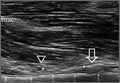
Biomechanical Evaluation of Two Arthroscopic Biceps Tenodesis Techniques: Proximal Interference Screw and Modified Percutaneous Intra-Articular Transtendon
Over the years, operative treatment of biceps pathology has escalated, likely secondary to increased identification and successful clinical outcomes. Although its true function remains controversial, the biceps tendon has been well accepted as a primary pain generator in the anterior aspect of the shoulder.1,2 Biceps pathology involves a spectrum of often overlapping findings—varying degrees of tearing, tendinitis, and instability. Pathology may be isolated or may present in association with other shoulder conditions, including impingement, bursitis, rotator cuff tears, SLAP (superior labral tear anterior to posterior) lesions, and acromioclavicular disorders.3
Operative treatment of disease of the long head of the biceps mandates an initial choice of tenotomy or tenodesis. Which approach is superior is controversial.4-6 Although tenotomy and tenodesis have comparably favorable clinical results, tenodesis is often recommended, particularly for younger, active patients, mostly because cosmetic deformity is possible with tenotomy.
Tenodesis may be performed arthroscopically or through an open incision, and the biceps tendon may be placed anywhere from in the joint to under the tendon of the pectoralis major tendon. In many recent biomechanical studies, interference screws had higher load to failure and improved stiffness in comparison with other fixation methods.7-19 Most of those studies focused on fixation in a subpectoral location. To our knowledge, only 2 studies of soft-tissue fixation have compared the percutaneous intra-articular transtendon (PITT) technique with other popular tenodesis techniques.20,21 The PITT technique demonstrated a common failure point, with sutures pulling through the tendon substance. It was hypothesized that adding a locking loop to the PITT suture configuration would further improve fixation.
We conducted a study to compare the biomechanical characteristics of 2 techniques for all-arthroscopic proximal biceps tenodesis: bioabsorbable interference screw (Biceptor; Smith & Nephew) and a locking-loop PITT modification developed at our institution.
Methods
Sixteen nonembalmed fresh-frozen human cadaveric shoulders (8 pairs: 3 male, 5 female) were used in this study. Mean specimen age was 55 years (range, 51-59 years). The specimens showed no evidence of high-grade osteoarthritic changes, biceps tendon fraying or tearing, biceps pulley lesions, or full-thickness rotator cuff tears. They were thawed at room temperature for 24 hours before the procedure.
In each pair, 1 shoulder was randomized to be treated with 1 of 2 arthroscopic biceps tenodesis techniques—modified PITT or Biceptor interference screw—and the other shoulder was treated with the other technique. Surgery was performed in an open fashion, and every attempt was made to simulate the arthroscopic approach. In all shoulders, biomechanical testing was completed immediately after tenodesis.
Modified PITT Technique
In an outside-in fashion, an 18-gauge spinal needle was used to pierce the transverse humeral ligament, the lateral aspect of the rotator interval tissue, and the biceps tendon. A second needle was then passed in similar fashion, piercing the biceps tendon just adjacent to the first needle (Figure 1A). A 0-polydioxanone monofilament suture (0-PDS; Ethicon, Johnson & Johnson) was threaded through the first needle and used to shuttle a single No. 2 braided nonabsorbable polyethylene suture (MaxBraid; Biomet Sports Medicine) back through the biceps tendon.
At this point, the free end of the nonabsorbable suture, which comes out of the anterior cannula during an arthroscopic procedure, was passed back into the glenohumeral joint (using a suture grasper), looped over the top of the biceps tendon, and brought back out of the joint anteriorly, thereby creating a locking loop around the tendon (Figure 1B). A shuttle suture (0-PDS) passed through the second needle was used to bring that anterior limb of nonabsorbable suture back through the biceps tendon, completing the stitch configuration (Figure 1C).
This process was repeated with another nonabsorbable suture. After suture passing was completed, the biceps was detached from its insertion at the superior labrum. The 2 nonabsorbable sutures, which would later be retrieved from the subacromial space, were then tied in standard fashion, securing the biceps tendon to the transverse humeral ligament/rotator interval tissue (Figure 1D).
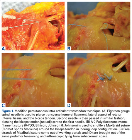
Biceptor Interference Screw Technique
The interference screw technique was performed in accordance with the manufacturer’s operative instructions.22 An 8 × 25-mm polyetheretherketone interference screw was used in all specimens, and the medium tendon fork was used to maintain tension on the biceps tendon during fixation (Figure 2A).
A 2.4-mm guide wire was inserted perpendicular to the humeral shaft, at the planned site of tenodesis, 10 mm distal to the entrance of the bicipital groove. An 8-mm cannulated reamer was passed over the wire, and a 30-mm tunnel was drilled (Figure 2B). The proximal part of the tendon was advanced into the center of the tunnel using the tendon fork (Figure 2C), and the tendon was held at the bottom of the tunnel with a 1.5-mm guide pin. The tendon fork was removed, and the cannulated interference screw was inserted over the guide pin between the 2 limbs of the biceps tendon (Figure 2D). The tendon was closely monitored to ensure it was not wrapped up when the screw was placed.
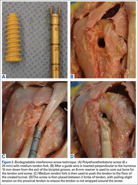
Biomechanical Testing
After each tenodesis, the humerus was amputated 5 inches distal to the fixation site. All extraneous soft tissue was dissected away, leaving the distal aspect of the biceps tendon as a free graft. Each proximal humerus–biceps tendon construct was then mounted on a materials testing machine. A custom-designed soft-tissue clamp was used to secure the distal aspect of the biceps tendon to the test actuator and load cell (Figure 3A). A custom-designed jig was used to stabilize the proximal humerus to the platform of the materials testing machine (Figure 3B). The specimens were mounted so that the line of pull throughout the testing protocol was applied parallel to the long axis of the humerus, thereby approximating the in vivo biceps force vector (Figure 3C). Digital cameras recorded each test for analysis of the mechanism of failure for each specimen. Marker dots were drawn on each tendon to assess tendon stretch before construct failure.
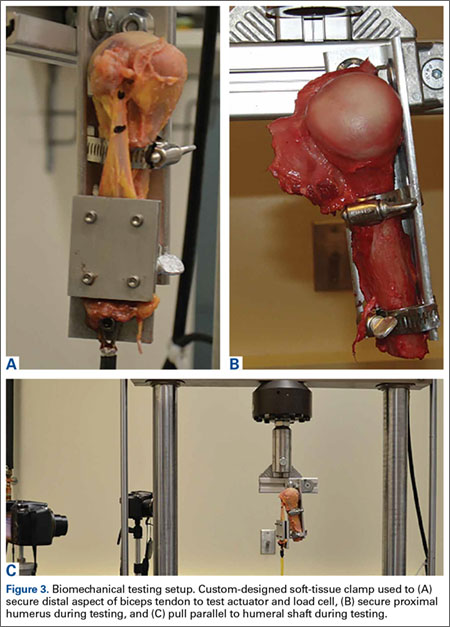
The tendons were preloaded to 10 N and then cycled at 0 to 50 N for 100 cycles at 1 Hz. After cyclic loading, axial load to failure was performed at a rate of 1.0 mm per second until a peak load was observed and subsequent loading led to tendon elongation with no further increase in load. Displacement and force applied during cyclic loading and load to failure were recorded. Stiffness was then calculated as the slope of the linear portion of the force-displacement curve using the least mean squares approach. Mechanism of failure was documented for each specimen.
Statistical Analysis
Analyzing our preliminary data with G*Power, we determined that a total sample size of 8 would be required (effect size [Cohen dz] was 1, α error probability was .05, power was .8). We hypothesized that the ultimate strength and stiffness of one group would be less than 1 SD above those of the other group. Paired t test with significance set at P < .05 was used to compare the techniques.
Results
Both repair constructs exhibited standard load-displacement curves, with a linear increase in load with displacement until the point of failure, at which time further displacement occurred with no discernible increase in load (Figure 4). Ultimate load to failure is determined as the highest point of the curve, and stiffness is calculated as the slope of the load-displacement curve.
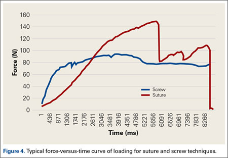
Mean axial displacement parallel to the shaft of the humerus with cyclic loading was 7.1 mm with the modified PITT technique and 7.9 mm with the interference screw technique. There was no macroscopically visible high-grade tearing or slippage of the biceps tendon in any specimen with cyclic loading for either repair construct.
Mean (SD) ultimate load to failure was significantly (P = .003) higher with the modified PITT technique, 157 (41) N, than with the interference screw technique, 107 (29) N; actual effect size (Cohen dz) was 1.19, difference of means was 50 N, and pooled SD was 42 N. The interference screw technique yielded significantly (P = .010) more mean (SD) stiffness, 38.7 (14.7) N/mm, than the modified PITT technique, 15.8 (9.1) N/mm; actual effect size (Cohen dz) was 1.37, difference of means was 22.9 N/mm, and pooled SD was 16.7 N/mm.
In the interference screw technique, the mode of failure was consistent. Of the 8 specimens, 7 failed at the screw–tendon interface at the distal aspect of the tunnel; in the eighth specimen, the entire tendon pulled out from under the screw construct. In the modified PITT technique, there was more variability in failure: tendon slipped through suture (4 specimens), tendon/suture construct as unit pulled through transverse ligament/rotator interval tissue (3), and suture failure (1).
Discussion
This study was the first to directly compare a bony interference screw technique with a soft-tissue technique (modified PITT). Fixation strength is crucial. A load of 112 N is applied to the long head of the biceps tendon when a person holds 1 kg of weight in the hand with the elbow at 90° flexion.22 As mean (SD) ultimate load to failure was 157 (41) N with the modified PITT technique and 107 (29) N with the interference screw technique in this study, the interference screw can be recommended only with some hesitation.
The interference screw was stiffer with cyclic loading—an expected outcome, as it was secured to rigid bone—vs soft tissue, as in the modified PITT technique. Although the clinical implications for the modified PITT technique are unknown, more than likely, with the tendon being secured to soft tissue, there will be scarring over time.
In laboratory testing of biceps tenodesis constructs, interference screw fixation has had superior load-to-failure characteristics in comparisons with other fixation methods. Golish and colleagues13 found significantly higher load to failure with a biotenodesis screw than with a double-loaded suture anchor for subpectoral tenodesis. Testing similar implants, in a location more proximal in the bicipital groove, Richards and Burkhart14 likewise found superior fixation strength with an interference screw. Ozalay and colleagues16 found superior strength in an interference screw compared with suture anchor, keyhole, and bone tunnel in sheep. In a pig model, the highest ultimate load to failure was found in an interference screw—vs keyhole, bone tunnel, suture anchor, and ligament washer.19 Load to failure for the interference screw in these studies ranged from 170 N to over 400 N.13,14,16,19
A few other investigators have studied the Biceptor interference screw. Slabaugh and colleagues15 found a mean (SD) load to failure of 173.9 (27.2) N for all specimens tested. Patzer and colleagues9,17 found that the mean (SD) ultimate load to failure with the Biceptor proximal interference screw, 173.9 (27.2) N, was superior to that of a suture anchor.
The mean (SD) ultimate load to failure reported for the Biceptor interference screw in the present study, 107 (29) N, is lower than the values reported in the other studies—not only for the Biceptor screw but for interference screws in general. Nevertheless, we performed the technique as the manufacturer recommended.22 Our results were consistent across all specimens studied. Interestingly, in the study by Slabaugh and colleagues,15 7 specimens failed at the tendon–screw interface during cyclic testing and were not included in the analysis of ultimate load to failure. As these specimens failed at a load between 5 N and 70 N, including their data would have significantly lowered the mean load to failure.
Concern over the Biceptor interference screw’s lower failure load relative to that of other interference screws has been raised before.9,17 A major issue is possible overstuffing of the humeral tunnel, as the hole is reamed the same size as the screw. With the Biceptor, the proximal and distal portions of the tendon are placed in the tunnel in a U-shaped configuration with the screw between these limbs. The idea is that the 2 biceps tendon limbs might become abraded and consecutively weaken as the screw is inserted between the tendon limbs, more so than with a single loop. This idea was suggested by the typical longitudinal tendon splitting that occurs at the screw–tendon interface at the distal aspect of the tunnel.23 In the present study, consistent failure (Figures 5A-5C) at the distal aspect of the screw–tendon junction supported the idea that the tendon is abraded during placement of the interference screw or during the friction-causing 90° turn the tendon takes into the bone on loading. There is no way to quantitatively examine tendon quality before interference screw placement, but on gross inspection all the tendons were of good quality. Slabaugh and colleagues15 also found consistent failure at the screw–tunnel interface.
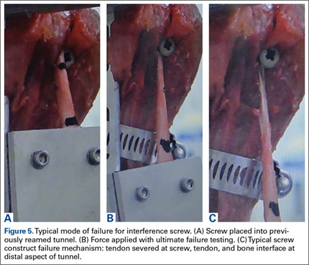
The PITT technique has been described as a simple all-arthroscopic soft-tissue technique for biceps tenodesis.23,24 Subsequently developed soft-tissue techniques have demonstrated clinical benefits.25-27 Proposed advantages of these techniques are lower cost associated with decreased implant needs, no reliance on quality of bone for fixation, suturing while biceps tendon is still attached to anchor (anatomical tension is closely reproduced), and less interference with any subsequent use of magnetic resonance imaging for diagnostic purposes in the shoulder.
There have been only 2 biomechanical studies of the PITT technique. Lopez-Vidriero and colleagues20 compared the biomechanical properties of the PITT and suture anchor techniques in a human cadaveric laboratory study and found that the PITT technique had mean (SD) ultimate load to failure of 142.7 (30.9) N and mean (SD) stiffness of 13.3 (3) N/mm. They observed consistent suture pullout through the tendon substance during failure, which suggests the most important factor for strength is the quality of the biceps tendon. Su and colleagues21 found biomechanically inferior results of the classic PITT technique as compared with the interference screw technique.
This article provides the first description of the modified PITT technique. Our mean (SD) load to failure of the modified PITT technique was 157 (41) N, slightly higher than that reported for the classic PITT technique, albeit under a different setup.20 There was more variation in ultimate load to failure in our study than in previous studies, which could be secondary to tissue quality. As the modified PITT technique relies on surrounding tissue holding the biceps in place, this tissue would need to be of good quality and strength to obtain strong fixation. A possible concern is that placing stitches in the rotator interval could increase the risk of shoulder stiffness, but this has not been encountered clinically.
A more variable mechanism of failure was also found in the present study. Although half the specimens failed by suture pullout through the tendon, similar to what Lopez-Vidriero and colleagues20 described, 3 of our 8 specimens failed with the entire biceps tendon–suture construct pulling through the transverse ligament tissue, and 1 specimen failed by suture breakage. Although these numbers are too small for making definitive statements, our modified PITT technique may add some security to the tendon–suture construct. Such added security may be of particular value in the setting of poor-quality, diseased tendon tissue, and the construct may be more limited by the strength of surrounding tissues. In addition, if failure occurs at the suture transverse humeral ligament–rotator interval interface, more surrounding rotator interval tissue can be incorporated into the tenodesis to decrease the likelihood of failure through this mechanism.
This study had several limitations. First, it was a time zero study in a cadaveric model with simulated biomechanical loading. As such, it provided information only on initial fixation strength and could not prove any superior clinical outcomes or account for any biological changes with healing that occurred over time. Second, the study may have been underpowered, though sample size was chosen in accordance with other cadaveric biomechanical studies. Third, all procedures were performed in an open manner, simulating the arthroscopic approach. Particularly in the setting of the modified PITT technique, this represented a best case scenario. Spinal needles and subsequent sutures were easily passed under direct visualization through the transverse humeral ligament, rotator interval, and biceps tendon. There is likely marked variability in this step during arthroscopy in which visualization is more limited, as in the setting of concomitant procedures, such as subacromial decompression or rotator cuff repair. In addition, all tendons tested were normal in appearance and gave no indication of chronic degenerative changes.
Another study limitation is that we did not quantify bone mineral density, which if poor would have affected interference screw strength. However, mean specimen age was 55 years, minimizing chances of poor bone quality. In addition, 7 of the 8 failures in the interference screw group occurred not with pullout but at the screw–tendon junction, suggesting poor bone quality was not a significant factor. As tendon diameter was not measured before the procedures were performed, there is the possibility it could have been better in the modified PITT group and worse in the interference screw group because of tunnel crowding, as noted.
1. Alpantaki K, McLaughlin D, Karagogeos D, Hadjipavlou A, Kontakis G. Sympathetic and sensory neural elements in the tendon of the long head of the biceps. J Bone Joint Surg Am. 2005;87(7):1580-1583.
2. Nho SJ, Strauss EJ, Lenart BA, et al. Long head of the biceps tendinopathy: diagnosis and management. J Am Acad Orthop Surg. 2010;18(11):645-656.
3. Khazzam M, George MS, Churchill RS, Kuhn JE. Disorders of the long head of biceps tendon. J Shoulder Elbow Surg. 2012;21(1):136-145.
4. Frost A, Zafar MS, Maffulli N. Tenotomy versus tenodesis in the management of pathologic lesions of the tendon of the long head of the biceps brachii. Am J Sports Med. 2009;37(4):828-833.
5. Hsu AR, Ghodadra NS, Provencher MT, Lewis PB, Bach BR. Biceps tenotomy versus tenodesis: a review of clinical outcomes and biomechanical results. J Shoulder Elbow Surg. 2011;20(2):326-332.
6. Slenker NR, Lawson K, Ciccotti MG, Dodson CC, Cohen SB. Biceps tenotomy versus tenodesis: clinical outcomes. Arthroscopy. 2012;28(4):576-582.
7. Mazzocca AD, Bicos J, Santangelo S, Romeo AA, Arciero RA. The biomechanical evaluation of four fixation techniques for proximal biceps tenodesis. Arthroscopy. 2005;21(11):1296-1306.
8. Millett PJ, Sanders B, Gobezie R, Braun S, Warner JJ. Interference screw vs. suture anchor fixation for open subpectoral biceps tenodesis: does it matter? BMC Musculoskelet Disord. 2008;9:121.
9. Patzer T, Rundic JM, Bobrowitsch E, Olender GD, Hurschler C, Schofer MD. Biomechanical comparison of arthroscopically performable techniques for suprapectoral biceps tenodesis. Arthroscopy. 2011;27(8):1036-1047.
10. Provencher MT, LeClere LE, Romeo AA. Subpectoral biceps tenodesis. Sports Med Arthrosc. 2008;16(3):170-176.
11. Mazzocca AD, Cote MP, Arciero CL, Romeo AA, Arciero RA. Clinical outcomes after subpectoral biceps tenodesis with an interference screw. Am J Sports Med. 2008;36(10):1922-1929.
12. Klepps S, Hazrati Y, Flatow E. Arthroscopic biceps tenodesis. Arthroscopy. 2002;18(9):1040-1045.
13. Golish SR, Caldwell PE 3rd, Miller MD, et al. Interference screw versus suture anchor fixation for subpectoral tenodesis of the proximal biceps tendon: a cadaveric study. Arthroscopy. 2008;24(10):1103-1108.
14. Richards DP, Burkhart SS. A biomechanical analysis of two biceps tenodesis fixation techniques. Arthroscopy. 2005;21(7):861-866.
15. Slabaugh MA, Frank RM, Van Thiel GS, et al. Biceps tenodesis with interference screw fixation: a biomechanical comparison of screw length and diameter. Arthroscopy. 2011;27(2):161-166.
16. Ozalay M, Akpinar S, Karaeminogullari O, et al. Mechanical strength of four different biceps tenodesis techniques. Arthroscopy. 2005;21(8):992-998.
17. Patzer T, Santo G, Olender GD, Wellmann M, Hurschler C, Schofer MD. Suprapectoral or subpectoral position for biceps tenodesis: biomechanical comparison of four different techniques in both positions. J Shoulder Elbow Surg. 2012;21(1):116-125.
18. Jayamoorthy T, Field JR, Costi JJ, Martin DK, Stanley RM, Hearn TC. Biceps tenodesis: a biomechanical study of fixation methods. J Shoulder Elbow Surg. 2004;13(2):160-164.
19. Kusma M, Dienst M, Eckert J, Steimer O, Kohn D. Tenodesis of the long head of biceps brachii: cyclic testing of five methods of fixation in a porcine model. J Shoulder Elbow Surg. 2008;17(6):967-973.
20. Lopez-Vidriero E, Costic RS, Fu FH, Rodosky MW. Biomechanical evaluation of 2 arthroscopic biceps tenodeses: double anchor versus percutaneous intra-articular transtendon (PITT) techniques. Am J Sports Med. 2010;38(1):146-152.
21. Su WR, Budoff JE, Chiang CH, Lee CJ, Lin CL. Biomechanical study comparing biceps wedge tenodesis with other proximal long head of the biceps tenodesis techniques. Arthroscopy. 2013;29(9):1498-1505.
22. Trenhaile SW. Biceptor Tenodesis System, Arthroscopic Biceps Tenodesis [operational instructions]. Andover, MA: Smith & Nephew; 2009:1-8.
23. Sekiya LC, Elkousy HA, Rodosky MW. Arthroscopic biceps tenodesis using the percutaneous intra-articular transtendon technique. Arthroscopy. 2003;19(10):1137-1141.
24. Elkousy HA, Fluhme DJ, O’Connor DP, Rodosky MW. Arthroscopic biceps tenodesis using the percutaneous, intra-articular trans-tendon technique: preliminary results. Orthopedics. 2005;28(11):1316-1319.
25. Castagna A, Conti M, Mouhsine E, Bungaro P, Garofalo R. Arthroscopic biceps tendon tenodesis; the anchorage technical note. Knee Surg Sports Traumatol Arthrosc. 2006;14(6):581-585.
26. Checchia SL, Doneux PS, Miyazaki AN, et al. Biceps tenodesis associated with arthroscopic repair of rotator cuff tears. J Shoulder Elbow Surg. 2005;14(2):138-144.
27. Moros C, Levine WN, Ahmad CS. Suture anchor and percutaneous intra-articular transtendon biceps tenodesis. Sports Med Arthrosc. 2008;16(3):177-179.
Over the years, operative treatment of biceps pathology has escalated, likely secondary to increased identification and successful clinical outcomes. Although its true function remains controversial, the biceps tendon has been well accepted as a primary pain generator in the anterior aspect of the shoulder.1,2 Biceps pathology involves a spectrum of often overlapping findings—varying degrees of tearing, tendinitis, and instability. Pathology may be isolated or may present in association with other shoulder conditions, including impingement, bursitis, rotator cuff tears, SLAP (superior labral tear anterior to posterior) lesions, and acromioclavicular disorders.3
Operative treatment of disease of the long head of the biceps mandates an initial choice of tenotomy or tenodesis. Which approach is superior is controversial.4-6 Although tenotomy and tenodesis have comparably favorable clinical results, tenodesis is often recommended, particularly for younger, active patients, mostly because cosmetic deformity is possible with tenotomy.
Tenodesis may be performed arthroscopically or through an open incision, and the biceps tendon may be placed anywhere from in the joint to under the tendon of the pectoralis major tendon. In many recent biomechanical studies, interference screws had higher load to failure and improved stiffness in comparison with other fixation methods.7-19 Most of those studies focused on fixation in a subpectoral location. To our knowledge, only 2 studies of soft-tissue fixation have compared the percutaneous intra-articular transtendon (PITT) technique with other popular tenodesis techniques.20,21 The PITT technique demonstrated a common failure point, with sutures pulling through the tendon substance. It was hypothesized that adding a locking loop to the PITT suture configuration would further improve fixation.
We conducted a study to compare the biomechanical characteristics of 2 techniques for all-arthroscopic proximal biceps tenodesis: bioabsorbable interference screw (Biceptor; Smith & Nephew) and a locking-loop PITT modification developed at our institution.
Methods
Sixteen nonembalmed fresh-frozen human cadaveric shoulders (8 pairs: 3 male, 5 female) were used in this study. Mean specimen age was 55 years (range, 51-59 years). The specimens showed no evidence of high-grade osteoarthritic changes, biceps tendon fraying or tearing, biceps pulley lesions, or full-thickness rotator cuff tears. They were thawed at room temperature for 24 hours before the procedure.
In each pair, 1 shoulder was randomized to be treated with 1 of 2 arthroscopic biceps tenodesis techniques—modified PITT or Biceptor interference screw—and the other shoulder was treated with the other technique. Surgery was performed in an open fashion, and every attempt was made to simulate the arthroscopic approach. In all shoulders, biomechanical testing was completed immediately after tenodesis.
Modified PITT Technique
In an outside-in fashion, an 18-gauge spinal needle was used to pierce the transverse humeral ligament, the lateral aspect of the rotator interval tissue, and the biceps tendon. A second needle was then passed in similar fashion, piercing the biceps tendon just adjacent to the first needle (Figure 1A). A 0-polydioxanone monofilament suture (0-PDS; Ethicon, Johnson & Johnson) was threaded through the first needle and used to shuttle a single No. 2 braided nonabsorbable polyethylene suture (MaxBraid; Biomet Sports Medicine) back through the biceps tendon.
At this point, the free end of the nonabsorbable suture, which comes out of the anterior cannula during an arthroscopic procedure, was passed back into the glenohumeral joint (using a suture grasper), looped over the top of the biceps tendon, and brought back out of the joint anteriorly, thereby creating a locking loop around the tendon (Figure 1B). A shuttle suture (0-PDS) passed through the second needle was used to bring that anterior limb of nonabsorbable suture back through the biceps tendon, completing the stitch configuration (Figure 1C).
This process was repeated with another nonabsorbable suture. After suture passing was completed, the biceps was detached from its insertion at the superior labrum. The 2 nonabsorbable sutures, which would later be retrieved from the subacromial space, were then tied in standard fashion, securing the biceps tendon to the transverse humeral ligament/rotator interval tissue (Figure 1D).
Biceptor Interference Screw Technique
The interference screw technique was performed in accordance with the manufacturer’s operative instructions.22 An 8 × 25-mm polyetheretherketone interference screw was used in all specimens, and the medium tendon fork was used to maintain tension on the biceps tendon during fixation (Figure 2A).
A 2.4-mm guide wire was inserted perpendicular to the humeral shaft, at the planned site of tenodesis, 10 mm distal to the entrance of the bicipital groove. An 8-mm cannulated reamer was passed over the wire, and a 30-mm tunnel was drilled (Figure 2B). The proximal part of the tendon was advanced into the center of the tunnel using the tendon fork (Figure 2C), and the tendon was held at the bottom of the tunnel with a 1.5-mm guide pin. The tendon fork was removed, and the cannulated interference screw was inserted over the guide pin between the 2 limbs of the biceps tendon (Figure 2D). The tendon was closely monitored to ensure it was not wrapped up when the screw was placed.
Biomechanical Testing
After each tenodesis, the humerus was amputated 5 inches distal to the fixation site. All extraneous soft tissue was dissected away, leaving the distal aspect of the biceps tendon as a free graft. Each proximal humerus–biceps tendon construct was then mounted on a materials testing machine. A custom-designed soft-tissue clamp was used to secure the distal aspect of the biceps tendon to the test actuator and load cell (Figure 3A). A custom-designed jig was used to stabilize the proximal humerus to the platform of the materials testing machine (Figure 3B). The specimens were mounted so that the line of pull throughout the testing protocol was applied parallel to the long axis of the humerus, thereby approximating the in vivo biceps force vector (Figure 3C). Digital cameras recorded each test for analysis of the mechanism of failure for each specimen. Marker dots were drawn on each tendon to assess tendon stretch before construct failure.
The tendons were preloaded to 10 N and then cycled at 0 to 50 N for 100 cycles at 1 Hz. After cyclic loading, axial load to failure was performed at a rate of 1.0 mm per second until a peak load was observed and subsequent loading led to tendon elongation with no further increase in load. Displacement and force applied during cyclic loading and load to failure were recorded. Stiffness was then calculated as the slope of the linear portion of the force-displacement curve using the least mean squares approach. Mechanism of failure was documented for each specimen.
Statistical Analysis
Analyzing our preliminary data with G*Power, we determined that a total sample size of 8 would be required (effect size [Cohen dz] was 1, α error probability was .05, power was .8). We hypothesized that the ultimate strength and stiffness of one group would be less than 1 SD above those of the other group. Paired t test with significance set at P < .05 was used to compare the techniques.
Results
Both repair constructs exhibited standard load-displacement curves, with a linear increase in load with displacement until the point of failure, at which time further displacement occurred with no discernible increase in load (Figure 4). Ultimate load to failure is determined as the highest point of the curve, and stiffness is calculated as the slope of the load-displacement curve.
Mean axial displacement parallel to the shaft of the humerus with cyclic loading was 7.1 mm with the modified PITT technique and 7.9 mm with the interference screw technique. There was no macroscopically visible high-grade tearing or slippage of the biceps tendon in any specimen with cyclic loading for either repair construct.
Mean (SD) ultimate load to failure was significantly (P = .003) higher with the modified PITT technique, 157 (41) N, than with the interference screw technique, 107 (29) N; actual effect size (Cohen dz) was 1.19, difference of means was 50 N, and pooled SD was 42 N. The interference screw technique yielded significantly (P = .010) more mean (SD) stiffness, 38.7 (14.7) N/mm, than the modified PITT technique, 15.8 (9.1) N/mm; actual effect size (Cohen dz) was 1.37, difference of means was 22.9 N/mm, and pooled SD was 16.7 N/mm.
In the interference screw technique, the mode of failure was consistent. Of the 8 specimens, 7 failed at the screw–tendon interface at the distal aspect of the tunnel; in the eighth specimen, the entire tendon pulled out from under the screw construct. In the modified PITT technique, there was more variability in failure: tendon slipped through suture (4 specimens), tendon/suture construct as unit pulled through transverse ligament/rotator interval tissue (3), and suture failure (1).
Discussion
This study was the first to directly compare a bony interference screw technique with a soft-tissue technique (modified PITT). Fixation strength is crucial. A load of 112 N is applied to the long head of the biceps tendon when a person holds 1 kg of weight in the hand with the elbow at 90° flexion.22 As mean (SD) ultimate load to failure was 157 (41) N with the modified PITT technique and 107 (29) N with the interference screw technique in this study, the interference screw can be recommended only with some hesitation.
The interference screw was stiffer with cyclic loading—an expected outcome, as it was secured to rigid bone—vs soft tissue, as in the modified PITT technique. Although the clinical implications for the modified PITT technique are unknown, more than likely, with the tendon being secured to soft tissue, there will be scarring over time.
In laboratory testing of biceps tenodesis constructs, interference screw fixation has had superior load-to-failure characteristics in comparisons with other fixation methods. Golish and colleagues13 found significantly higher load to failure with a biotenodesis screw than with a double-loaded suture anchor for subpectoral tenodesis. Testing similar implants, in a location more proximal in the bicipital groove, Richards and Burkhart14 likewise found superior fixation strength with an interference screw. Ozalay and colleagues16 found superior strength in an interference screw compared with suture anchor, keyhole, and bone tunnel in sheep. In a pig model, the highest ultimate load to failure was found in an interference screw—vs keyhole, bone tunnel, suture anchor, and ligament washer.19 Load to failure for the interference screw in these studies ranged from 170 N to over 400 N.13,14,16,19
A few other investigators have studied the Biceptor interference screw. Slabaugh and colleagues15 found a mean (SD) load to failure of 173.9 (27.2) N for all specimens tested. Patzer and colleagues9,17 found that the mean (SD) ultimate load to failure with the Biceptor proximal interference screw, 173.9 (27.2) N, was superior to that of a suture anchor.
The mean (SD) ultimate load to failure reported for the Biceptor interference screw in the present study, 107 (29) N, is lower than the values reported in the other studies—not only for the Biceptor screw but for interference screws in general. Nevertheless, we performed the technique as the manufacturer recommended.22 Our results were consistent across all specimens studied. Interestingly, in the study by Slabaugh and colleagues,15 7 specimens failed at the tendon–screw interface during cyclic testing and were not included in the analysis of ultimate load to failure. As these specimens failed at a load between 5 N and 70 N, including their data would have significantly lowered the mean load to failure.
Concern over the Biceptor interference screw’s lower failure load relative to that of other interference screws has been raised before.9,17 A major issue is possible overstuffing of the humeral tunnel, as the hole is reamed the same size as the screw. With the Biceptor, the proximal and distal portions of the tendon are placed in the tunnel in a U-shaped configuration with the screw between these limbs. The idea is that the 2 biceps tendon limbs might become abraded and consecutively weaken as the screw is inserted between the tendon limbs, more so than with a single loop. This idea was suggested by the typical longitudinal tendon splitting that occurs at the screw–tendon interface at the distal aspect of the tunnel.23 In the present study, consistent failure (Figures 5A-5C) at the distal aspect of the screw–tendon junction supported the idea that the tendon is abraded during placement of the interference screw or during the friction-causing 90° turn the tendon takes into the bone on loading. There is no way to quantitatively examine tendon quality before interference screw placement, but on gross inspection all the tendons were of good quality. Slabaugh and colleagues15 also found consistent failure at the screw–tunnel interface.
The PITT technique has been described as a simple all-arthroscopic soft-tissue technique for biceps tenodesis.23,24 Subsequently developed soft-tissue techniques have demonstrated clinical benefits.25-27 Proposed advantages of these techniques are lower cost associated with decreased implant needs, no reliance on quality of bone for fixation, suturing while biceps tendon is still attached to anchor (anatomical tension is closely reproduced), and less interference with any subsequent use of magnetic resonance imaging for diagnostic purposes in the shoulder.
There have been only 2 biomechanical studies of the PITT technique. Lopez-Vidriero and colleagues20 compared the biomechanical properties of the PITT and suture anchor techniques in a human cadaveric laboratory study and found that the PITT technique had mean (SD) ultimate load to failure of 142.7 (30.9) N and mean (SD) stiffness of 13.3 (3) N/mm. They observed consistent suture pullout through the tendon substance during failure, which suggests the most important factor for strength is the quality of the biceps tendon. Su and colleagues21 found biomechanically inferior results of the classic PITT technique as compared with the interference screw technique.
This article provides the first description of the modified PITT technique. Our mean (SD) load to failure of the modified PITT technique was 157 (41) N, slightly higher than that reported for the classic PITT technique, albeit under a different setup.20 There was more variation in ultimate load to failure in our study than in previous studies, which could be secondary to tissue quality. As the modified PITT technique relies on surrounding tissue holding the biceps in place, this tissue would need to be of good quality and strength to obtain strong fixation. A possible concern is that placing stitches in the rotator interval could increase the risk of shoulder stiffness, but this has not been encountered clinically.
A more variable mechanism of failure was also found in the present study. Although half the specimens failed by suture pullout through the tendon, similar to what Lopez-Vidriero and colleagues20 described, 3 of our 8 specimens failed with the entire biceps tendon–suture construct pulling through the transverse ligament tissue, and 1 specimen failed by suture breakage. Although these numbers are too small for making definitive statements, our modified PITT technique may add some security to the tendon–suture construct. Such added security may be of particular value in the setting of poor-quality, diseased tendon tissue, and the construct may be more limited by the strength of surrounding tissues. In addition, if failure occurs at the suture transverse humeral ligament–rotator interval interface, more surrounding rotator interval tissue can be incorporated into the tenodesis to decrease the likelihood of failure through this mechanism.
This study had several limitations. First, it was a time zero study in a cadaveric model with simulated biomechanical loading. As such, it provided information only on initial fixation strength and could not prove any superior clinical outcomes or account for any biological changes with healing that occurred over time. Second, the study may have been underpowered, though sample size was chosen in accordance with other cadaveric biomechanical studies. Third, all procedures were performed in an open manner, simulating the arthroscopic approach. Particularly in the setting of the modified PITT technique, this represented a best case scenario. Spinal needles and subsequent sutures were easily passed under direct visualization through the transverse humeral ligament, rotator interval, and biceps tendon. There is likely marked variability in this step during arthroscopy in which visualization is more limited, as in the setting of concomitant procedures, such as subacromial decompression or rotator cuff repair. In addition, all tendons tested were normal in appearance and gave no indication of chronic degenerative changes.
Another study limitation is that we did not quantify bone mineral density, which if poor would have affected interference screw strength. However, mean specimen age was 55 years, minimizing chances of poor bone quality. In addition, 7 of the 8 failures in the interference screw group occurred not with pullout but at the screw–tendon junction, suggesting poor bone quality was not a significant factor. As tendon diameter was not measured before the procedures were performed, there is the possibility it could have been better in the modified PITT group and worse in the interference screw group because of tunnel crowding, as noted.
1. Alpantaki K, McLaughlin D, Karagogeos D, Hadjipavlou A, Kontakis G. Sympathetic and sensory neural elements in the tendon of the long head of the biceps. J Bone Joint Surg Am. 2005;87(7):1580-1583.
2. Nho SJ, Strauss EJ, Lenart BA, et al. Long head of the biceps tendinopathy: diagnosis and management. J Am Acad Orthop Surg. 2010;18(11):645-656.
3. Khazzam M, George MS, Churchill RS, Kuhn JE. Disorders of the long head of biceps tendon. J Shoulder Elbow Surg. 2012;21(1):136-145.
4. Frost A, Zafar MS, Maffulli N. Tenotomy versus tenodesis in the management of pathologic lesions of the tendon of the long head of the biceps brachii. Am J Sports Med. 2009;37(4):828-833.
5. Hsu AR, Ghodadra NS, Provencher MT, Lewis PB, Bach BR. Biceps tenotomy versus tenodesis: a review of clinical outcomes and biomechanical results. J Shoulder Elbow Surg. 2011;20(2):326-332.
6. Slenker NR, Lawson K, Ciccotti MG, Dodson CC, Cohen SB. Biceps tenotomy versus tenodesis: clinical outcomes. Arthroscopy. 2012;28(4):576-582.
7. Mazzocca AD, Bicos J, Santangelo S, Romeo AA, Arciero RA. The biomechanical evaluation of four fixation techniques for proximal biceps tenodesis. Arthroscopy. 2005;21(11):1296-1306.
8. Millett PJ, Sanders B, Gobezie R, Braun S, Warner JJ. Interference screw vs. suture anchor fixation for open subpectoral biceps tenodesis: does it matter? BMC Musculoskelet Disord. 2008;9:121.
9. Patzer T, Rundic JM, Bobrowitsch E, Olender GD, Hurschler C, Schofer MD. Biomechanical comparison of arthroscopically performable techniques for suprapectoral biceps tenodesis. Arthroscopy. 2011;27(8):1036-1047.
10. Provencher MT, LeClere LE, Romeo AA. Subpectoral biceps tenodesis. Sports Med Arthrosc. 2008;16(3):170-176.
11. Mazzocca AD, Cote MP, Arciero CL, Romeo AA, Arciero RA. Clinical outcomes after subpectoral biceps tenodesis with an interference screw. Am J Sports Med. 2008;36(10):1922-1929.
12. Klepps S, Hazrati Y, Flatow E. Arthroscopic biceps tenodesis. Arthroscopy. 2002;18(9):1040-1045.
13. Golish SR, Caldwell PE 3rd, Miller MD, et al. Interference screw versus suture anchor fixation for subpectoral tenodesis of the proximal biceps tendon: a cadaveric study. Arthroscopy. 2008;24(10):1103-1108.
14. Richards DP, Burkhart SS. A biomechanical analysis of two biceps tenodesis fixation techniques. Arthroscopy. 2005;21(7):861-866.
15. Slabaugh MA, Frank RM, Van Thiel GS, et al. Biceps tenodesis with interference screw fixation: a biomechanical comparison of screw length and diameter. Arthroscopy. 2011;27(2):161-166.
16. Ozalay M, Akpinar S, Karaeminogullari O, et al. Mechanical strength of four different biceps tenodesis techniques. Arthroscopy. 2005;21(8):992-998.
17. Patzer T, Santo G, Olender GD, Wellmann M, Hurschler C, Schofer MD. Suprapectoral or subpectoral position for biceps tenodesis: biomechanical comparison of four different techniques in both positions. J Shoulder Elbow Surg. 2012;21(1):116-125.
18. Jayamoorthy T, Field JR, Costi JJ, Martin DK, Stanley RM, Hearn TC. Biceps tenodesis: a biomechanical study of fixation methods. J Shoulder Elbow Surg. 2004;13(2):160-164.
19. Kusma M, Dienst M, Eckert J, Steimer O, Kohn D. Tenodesis of the long head of biceps brachii: cyclic testing of five methods of fixation in a porcine model. J Shoulder Elbow Surg. 2008;17(6):967-973.
20. Lopez-Vidriero E, Costic RS, Fu FH, Rodosky MW. Biomechanical evaluation of 2 arthroscopic biceps tenodeses: double anchor versus percutaneous intra-articular transtendon (PITT) techniques. Am J Sports Med. 2010;38(1):146-152.
21. Su WR, Budoff JE, Chiang CH, Lee CJ, Lin CL. Biomechanical study comparing biceps wedge tenodesis with other proximal long head of the biceps tenodesis techniques. Arthroscopy. 2013;29(9):1498-1505.
22. Trenhaile SW. Biceptor Tenodesis System, Arthroscopic Biceps Tenodesis [operational instructions]. Andover, MA: Smith & Nephew; 2009:1-8.
23. Sekiya LC, Elkousy HA, Rodosky MW. Arthroscopic biceps tenodesis using the percutaneous intra-articular transtendon technique. Arthroscopy. 2003;19(10):1137-1141.
24. Elkousy HA, Fluhme DJ, O’Connor DP, Rodosky MW. Arthroscopic biceps tenodesis using the percutaneous, intra-articular trans-tendon technique: preliminary results. Orthopedics. 2005;28(11):1316-1319.
25. Castagna A, Conti M, Mouhsine E, Bungaro P, Garofalo R. Arthroscopic biceps tendon tenodesis; the anchorage technical note. Knee Surg Sports Traumatol Arthrosc. 2006;14(6):581-585.
26. Checchia SL, Doneux PS, Miyazaki AN, et al. Biceps tenodesis associated with arthroscopic repair of rotator cuff tears. J Shoulder Elbow Surg. 2005;14(2):138-144.
27. Moros C, Levine WN, Ahmad CS. Suture anchor and percutaneous intra-articular transtendon biceps tenodesis. Sports Med Arthrosc. 2008;16(3):177-179.
Is a Persistent Vacuum Phenomenon a Sign of Pseudarthrosis After Posterolateral Spinal Fusion?
The spinal vacuum sign or vacuum phenomenon (VP) is the radiographic finding of an air-density linear radiolucency in the intervertebral disc or vertebral body. The result of a gaseous accumulation, it is often a diagnostic sign of disc degeneration as well as a rare sign of infection, Schmorl node formation, or osteonecrosis.1,2 Although the VP was first described on plain radiographs, it is better seen on computed tomography (CT).3 Multiple studies have found a possible association between the VP and nonunion in diaphyseal fractures,4 ankylosing spondylitis,5,6 and lumbar spinal fusion.7
To our knowledge, no one has studied whether the intervertebral VP resolves after posterolateral lumbar spinal fusion in adults with degenerative spinal pathology, and no one has investigated the association between the persistence of the intervertebral VP and pseudarthrosis after posterolateral spinal fusion.
We conducted a study to determine whether the VP resolves after posterolateral lumbar spinal fusion procedures and whether persistence of the VP after fusion surgery is indicative of pseudarthrosis.
Materials and Methods
After obtaining Institutional Review Board approval for this study, we retrospectively reviewed the medical records of patients who had degenerative spinal stenosis with instability and the intervertebral vacuum sign on preoperative digital lumbar spine CT scans and who underwent posterolateral lumbar spinal fusion with or without instrumentation. Study inclusion criteria were lumbar spine CT at minimum 6-month follow-up after spinal fusion and preoperative and postoperative lumbar spine radiographs. Exclusion criteria were any type of interbody fusion procedure (anterior, posterior, transforaminal, lateral) at a level with the VP, age under 21 years, follow-up of less than 6 months, and incomplete radiographic records. As this was a retrospective study, patient consent was not required.
CT was performed with a 16-, 64-, or 128-slice multidetector CT scanner with effective tube current set at 250 to 320 mA, voltage set at 120 to 140 kV, and pitch set at 0.75 to 0.9. After axial acquisition of 3×3-mm isometric voxels, sagittal and coronal multiplanar images were reconstructed with a slice thickness of 2 mm. Patient demographics, diagnoses, and surgical details were recorded. All digital lumbar spine CT scans and radiographs were initially screened on PACS (picture archiving and communication system) by the orthopedic spine surgery fellow at an academic medical institution; then they were reviewed on a radiology reading room monitor by 3 observers (senior radiologist, senior orthopedic spine surgeon, orthopedic spine surgery fellow). Axial images and sagittal and coronal reconstructed images of the preoperative and postoperative follow-up lumbar CT scans—together with the lateral and anteroposterior lumbar spine radiographs—were evaluated for the intervertebral VP. Mean (SD) follow-up (with CT to assess fusion) was 1.6 (0.86) years (range, 0.75-3.38 years). Fusion at each level was evaluated on the postoperative follow-up CT on axial images and sagittal and coronal reconstructed images; criteria for fusion were continuous bridging bone across posterolateral gutters and facets on one or both sides at each intervertebral level.8 Pseudarthrosis was recorded if there was no continuity of bridging bone across both posterolateral gutters and facets, a complete radiolucent line on both sides across a level, or lysis or loosening around screws. All recordings were made by consensus, or by majority decision in case of disagreement.
Presence of the VP at the lumbar levels not included in the fusion was also recorded on the preoperative and follow-up CT scan and radiographs.
Descriptive and inferential statistical tests were performed as applicable. Pearson χ2 test and Fischer exact test were used to evaluate if there was a significant association between the groups where the VP disappeared and persisted and fusion and pseudarthrosis. Significance was set at P < .05. Statistical analysis was performed with Stata Version 10.0.
Results
Using the preoperative lumbar spine CT scans of 18 patients (10 men, 8 women), we identified 36 cases of intervertebral levels exhibiting the VP (median positive vacuum sign levels per patient, 2; minimum, 1; maximum, 5) at the levels included in the fusion (Table 1). Mean (SD) age at surgery was 67.6 (9.4) years (range, 46.5-79.6 years). Mean (SD) radiologic follow-up was 1.6 (0.86) years (range, 0.75-3.38 years). All patients underwent lumbar fusion with local autograft, allograft, and recombinant human bone morphogenetic protein 2. Spinal instrumentation was used in 16 of the 18 patients.
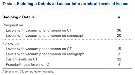
On preoperative CT, positive VP was diagnosed in the 36 cases as follows: L5–S1 (11 cases), L4–L5 (9 cases), L3–L4 (4 cases), L2–L3 (6 cases), L1–L2 (4 cases), and T12–L1 (2 cases). On follow-up CT, 15 cases showed persistence of the VP, and 21 cases showed disappearance of the VP (Table 1).
Evidence of spinal fusion was identified on follow-up CT in 32 (88.9%) of the 36 cases. In 3 of the 18 patients, nonunion was diagnosed. Of the 15 intervertebral cases in which the VP persisted, 13 (86.7%) showed evidence of fusion on CT, and 2 (13.3%) showed evidence of pseudarthrosis. Of the 21 intervertebral cases in which the VP disappeared, 19 (90.5%) showed evidence of fusion on CT, and 2 (9.5%) showed evidence of pseudarthrosis (Table 2). There was no significant difference in fusion rate or pseudarthrosis rate in the groups in which the VP persisted or disappeared (Fischer exact test, P = .99). There was no significant association between VP persistence or disappearance and sex, primary or revision surgery, or intervertebral level (Fischer exact test, P > .05). A case example is shown in the Figure.
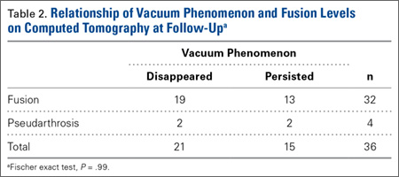
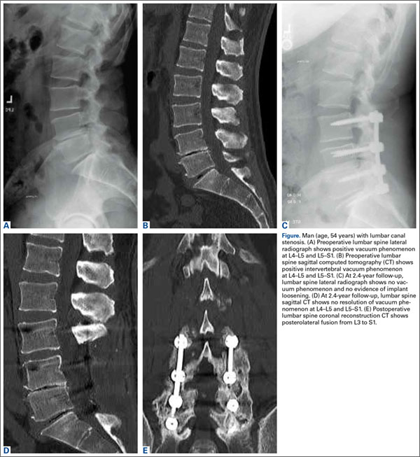
At levels not included in spinal fusion, CT identified the VP at 6 lumbar intervertebral levels before surgery and 11 levels at follow-up. The VP did not disappear at any level not included in the fusion. At follow-up, no new VP was identified in a segment included in fusion. Results are summarized in Table 3.
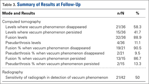
Discussion
The association of radiologic intervertebral VP and disc degeneration, first recognized by Knutsson1 in 1942, refers to the presence of gas, mainly containing nitrogen, in the crevices between or within vertebrae.2 The VP is more often seen in patients older than 50 years, on plain radiographs in hyperextension.9 CT is more sensitive than radiography in detecting the VP; Lardé and colleagues3 found it in about 50% of 50 patients on CT scans but in only 12% of patients on radiographs. The VP is visible because of the nitrogen gas that accumulates when there is a negative pressure within the disc space. Nitrogen emerges from the blood and moves into the disc space; perhaps the disc space opens, causing the negative pressure.1-3 On T1- or T2-weighted magnetic resonance imaging (MRI), the VP is visible as a signal void. MRI, however, is less accurate than CT.10 In a study of 10 patients who had low back pain and more than 1 level of intradiscal VP, and who underwent supine MRI examinations at 0, 1, and 2 hours, Wang and colleagues11 found that, after prolonged supine positioning, the signal intensity of the vacuum was replaced by hyperintense fluid contents. D’Anastasi and colleagues,12 in a study of 20 patients who had lumbar vacuum phenomenon on CT and underwent MRI examinations, found a significant correlation between presence of intradiscal fluid and amount of bone marrow edema on MRI and degenerative endplate abnormalities on CT. In the present study, we found that, after the spinal fusion vacuum phenomenon disappeared in 58.3% of the lumbar levels and persisted in 41.7% on follow-up CT at the levels included in posterolateral fusion, there were 5 new levels, adjacent to the lumbar fusion, where the VP was seen on the follow-up CT.
We studied whether evidence of a persistent vacuum sign on CT is indicative of pseudarthrosis. Other authors have reported an association between the VP and nonunion in fractures4 and ankylosing spondylitis.5,6 In a study of 19 patients with diaphyseal fractures, Stallenberg and colleagues4 found that, in 7 of the 10 patients with nonunion, the VP was detected on CT at the nonunion site. Martel5 first reported on the intervertebral VP in a case of ankylosing spondylitis with spinal pseudarthrosis. Ten years later, in a study of 18 patients with advanced ankylosing spondylitis with spinal pseudarthrosis, Chan and colleagues6 identified the intervertebral VP on CT in 7 patients. Edwards and colleagues7 studied 15 patients with prior lumbar fusion with 17 positive intervertebral VP levels on CT and found that the vacuum disc sign was a strong predictor of lumbar nonunion as determined by surgical exploration. Mirovsky and colleagues13 identified the intravertebral vacuum cleft in 26 patients with an osteoporotic vertebral fracture treated with vertebroplasty and concluded that nonunion of the vertebral fracture could be identified by presence of the intravertebral vacuum cleft on radiography. In the present study, there was radiologic evidence of lumbar spinal fusion in 89% of disc levels with a preoperative positive intervertebral VP and pseudarthrosis in 11% of disc levels. The rate of fusion at levels with the VP was comparable to the rate at intervertebral levels without the phenomenon. These findings indicate that persistence of the VP after spinal fusion is not an indication that fusion has not been achieved. Preoperative VP also did not predispose to failure of fusion. That there is a persistent vacuum disc might imply that, even after successful fusion as seen on CT, some motion may be occurring at the disc level to cause a negative pressure phenomenon. Even in cases of facet fusion with bridging bone, there may still be motion at the disc level, as fusions can plastically deform (even with screws in), particularly in elderly osteopenic bone. We found no association between a persistent vacuum sign and pseudarthrosis. Our study findings are clinically useful even if the benefits are limited. These findings may help surgeons avoid misinterpreting this sign as an indication for additional surgery.
This study had some limitations. First, radiographs were used to determine presence or absence of fusion. Although CT is widely considered the gold standard for noninvasive assessment of fusion,14 even when both posterolateral gutters and facets have been found to be fused on CT, the probability of a solid fusion on exploration ranges from 69% to 96%.8,15 Second, detection of the VP on radiographs and CT may be affected by patient position.11 Third, this was a retrospective series with a small number of patients and limited follow-up with CT. Arthrodesis and the VP may take years to fully evolve. It is possible that fusion rates could be higher on longer follow-up, and resolution of the VP may occur with longer follow-up. Fourth, clinical outcomes were not evaluated, as there are other confounding factors, apart from successful fusion, that could affect clinical outcomes. A larger prospective controlled study would be helpful.
Conclusion
The radiologic intervertebral VP may persist after posterolateral lumbar spinal fusion. We did not find an association between the VP and pseudarthrosis. In addition, VP persistence on follow-up CT was not indicative of pseudarthrosis, and VP disappearance was not indicative of fusion. The vacuum sign should not be misinterpreted as an indication for additional surgery.
1. Knutsson F. The vacuum phenomenon in the intervertebral discs. Acta Radiol. 1942;23:173-179.
2. Resnick D, Niwayama G, Guerra J Jr, Vint V, Usselman J. Spinal vacuum phenomenon: anatomical study and review. Radiology. 1981;139(2):341-348.
3. Lardé D, Mathieu D, Frija J, Gaston A, Vasile N. Spinal vacuum phenomenon: CT diagnosis and significance. J Comput Assist Tomogr. 1982;6(4):671-676.
4. Stallenberg B, Madani A, Burny F, Gevenois PA. The vacuum phenomenon: a CT sign of nonunited fracture. AJR Am J Roentgenol. 2001;176(5):1161-1164.
5. Martel W. Spinal pseudarthrosis: a complication of ankylosing spondylitis. Arthritis Rheum. 1978;21(4):485-490.
6. Chan FL, Ho EK, Chau EM. Spinal pseudarthrosis complicating ankylosing spondylitis: comparison of CT and conventional tomography. AJR Am J Roentgenol. 1988;150(3):611-614.
7. Edwards CE, Antonoiades SB, Ford L, Crabster E. CT vacuum disc sign: a highly specific predictor of lumbar nonunion. Poster presented at: 41st Annual Meeting of the Scoliosis Research Society; September 2006; Monterey, CA.
8. Carreon LY, Djurasovic M, Glassman SD, Sailer P. Diagnostic accuracy and reliability of fine-cut CT scans with reconstructions to determine the status of an instrumented posterolateral fusion with surgical exploration as reference standard. Spine. 2007;32(8):892-895.
9. Goobar JE, Pate D, Resnick D, Sartoris DJ. Radiography of the hyperextended lumbar spine: an effective technique for the demonstration of discal vacuum phenomena. Can Assoc Radiol J. 1987;38(4):271-274.
10. Grenier N, Grossman RI, Schiebler ML, Yeager BA, Goldberg HI, Kressel HY. Degenerative lumbar disk disease: pitfalls and usefulness of MR imaging in detection of vacuum phenomenon. Radiology. 1987;164(3):861-865.
11. Wang HJ, Chen BB, Yu CW, Hsu CY, Shih TT. Alteration of disc vacuum contents during prolonged supine positioning: evaluation with MR Image. Spine. 2007;32(23):2610-2615.
12. D’Anastasi M, Birkenmaier C, Schmidt GP, Wegener B, Reiser MF, Baur-Melnyk A. Correlation between vacuum phenomenon on CT and fluid on MRI in degenerative disks. AJR Am J Roentgenol. 2011;197(5):1182-1189.
13. Mirovsky Y, Anekstein Y, Shalmon E, Peer A. Vacuum clefts of the vertebral bodies. AJNR Am J Neuroradiol. 2005;26(7):1634-1640.
14. Selby MD, Clark SR, Hall DJ, Freeman BJ. Radiologic assessment of spinal fusion. J Am Acad Orthop Surg. 2012;20(11):694-703.
15. Kanayama M, Hashimoto T, Shigenobu K, Yamane S, Bauer TW, Togawa D. A prospective randomized study of posterolateral lumbar fusion using osteogenic protein-1 (OP-1) versus local autograft with ceramic bone substitute: emphasis of surgical exploration and histologic assessment. Spine. 2006;31(10):1067-1074.
The spinal vacuum sign or vacuum phenomenon (VP) is the radiographic finding of an air-density linear radiolucency in the intervertebral disc or vertebral body. The result of a gaseous accumulation, it is often a diagnostic sign of disc degeneration as well as a rare sign of infection, Schmorl node formation, or osteonecrosis.1,2 Although the VP was first described on plain radiographs, it is better seen on computed tomography (CT).3 Multiple studies have found a possible association between the VP and nonunion in diaphyseal fractures,4 ankylosing spondylitis,5,6 and lumbar spinal fusion.7
To our knowledge, no one has studied whether the intervertebral VP resolves after posterolateral lumbar spinal fusion in adults with degenerative spinal pathology, and no one has investigated the association between the persistence of the intervertebral VP and pseudarthrosis after posterolateral spinal fusion.
We conducted a study to determine whether the VP resolves after posterolateral lumbar spinal fusion procedures and whether persistence of the VP after fusion surgery is indicative of pseudarthrosis.
Materials and Methods
After obtaining Institutional Review Board approval for this study, we retrospectively reviewed the medical records of patients who had degenerative spinal stenosis with instability and the intervertebral vacuum sign on preoperative digital lumbar spine CT scans and who underwent posterolateral lumbar spinal fusion with or without instrumentation. Study inclusion criteria were lumbar spine CT at minimum 6-month follow-up after spinal fusion and preoperative and postoperative lumbar spine radiographs. Exclusion criteria were any type of interbody fusion procedure (anterior, posterior, transforaminal, lateral) at a level with the VP, age under 21 years, follow-up of less than 6 months, and incomplete radiographic records. As this was a retrospective study, patient consent was not required.
CT was performed with a 16-, 64-, or 128-slice multidetector CT scanner with effective tube current set at 250 to 320 mA, voltage set at 120 to 140 kV, and pitch set at 0.75 to 0.9. After axial acquisition of 3×3-mm isometric voxels, sagittal and coronal multiplanar images were reconstructed with a slice thickness of 2 mm. Patient demographics, diagnoses, and surgical details were recorded. All digital lumbar spine CT scans and radiographs were initially screened on PACS (picture archiving and communication system) by the orthopedic spine surgery fellow at an academic medical institution; then they were reviewed on a radiology reading room monitor by 3 observers (senior radiologist, senior orthopedic spine surgeon, orthopedic spine surgery fellow). Axial images and sagittal and coronal reconstructed images of the preoperative and postoperative follow-up lumbar CT scans—together with the lateral and anteroposterior lumbar spine radiographs—were evaluated for the intervertebral VP. Mean (SD) follow-up (with CT to assess fusion) was 1.6 (0.86) years (range, 0.75-3.38 years). Fusion at each level was evaluated on the postoperative follow-up CT on axial images and sagittal and coronal reconstructed images; criteria for fusion were continuous bridging bone across posterolateral gutters and facets on one or both sides at each intervertebral level.8 Pseudarthrosis was recorded if there was no continuity of bridging bone across both posterolateral gutters and facets, a complete radiolucent line on both sides across a level, or lysis or loosening around screws. All recordings were made by consensus, or by majority decision in case of disagreement.
Presence of the VP at the lumbar levels not included in the fusion was also recorded on the preoperative and follow-up CT scan and radiographs.
Descriptive and inferential statistical tests were performed as applicable. Pearson χ2 test and Fischer exact test were used to evaluate if there was a significant association between the groups where the VP disappeared and persisted and fusion and pseudarthrosis. Significance was set at P < .05. Statistical analysis was performed with Stata Version 10.0.
Results
Using the preoperative lumbar spine CT scans of 18 patients (10 men, 8 women), we identified 36 cases of intervertebral levels exhibiting the VP (median positive vacuum sign levels per patient, 2; minimum, 1; maximum, 5) at the levels included in the fusion (Table 1). Mean (SD) age at surgery was 67.6 (9.4) years (range, 46.5-79.6 years). Mean (SD) radiologic follow-up was 1.6 (0.86) years (range, 0.75-3.38 years). All patients underwent lumbar fusion with local autograft, allograft, and recombinant human bone morphogenetic protein 2. Spinal instrumentation was used in 16 of the 18 patients.
On preoperative CT, positive VP was diagnosed in the 36 cases as follows: L5–S1 (11 cases), L4–L5 (9 cases), L3–L4 (4 cases), L2–L3 (6 cases), L1–L2 (4 cases), and T12–L1 (2 cases). On follow-up CT, 15 cases showed persistence of the VP, and 21 cases showed disappearance of the VP (Table 1).
Evidence of spinal fusion was identified on follow-up CT in 32 (88.9%) of the 36 cases. In 3 of the 18 patients, nonunion was diagnosed. Of the 15 intervertebral cases in which the VP persisted, 13 (86.7%) showed evidence of fusion on CT, and 2 (13.3%) showed evidence of pseudarthrosis. Of the 21 intervertebral cases in which the VP disappeared, 19 (90.5%) showed evidence of fusion on CT, and 2 (9.5%) showed evidence of pseudarthrosis (Table 2). There was no significant difference in fusion rate or pseudarthrosis rate in the groups in which the VP persisted or disappeared (Fischer exact test, P = .99). There was no significant association between VP persistence or disappearance and sex, primary or revision surgery, or intervertebral level (Fischer exact test, P > .05). A case example is shown in the Figure.
At levels not included in spinal fusion, CT identified the VP at 6 lumbar intervertebral levels before surgery and 11 levels at follow-up. The VP did not disappear at any level not included in the fusion. At follow-up, no new VP was identified in a segment included in fusion. Results are summarized in Table 3.
Discussion
The association of radiologic intervertebral VP and disc degeneration, first recognized by Knutsson1 in 1942, refers to the presence of gas, mainly containing nitrogen, in the crevices between or within vertebrae.2 The VP is more often seen in patients older than 50 years, on plain radiographs in hyperextension.9 CT is more sensitive than radiography in detecting the VP; Lardé and colleagues3 found it in about 50% of 50 patients on CT scans but in only 12% of patients on radiographs. The VP is visible because of the nitrogen gas that accumulates when there is a negative pressure within the disc space. Nitrogen emerges from the blood and moves into the disc space; perhaps the disc space opens, causing the negative pressure.1-3 On T1- or T2-weighted magnetic resonance imaging (MRI), the VP is visible as a signal void. MRI, however, is less accurate than CT.10 In a study of 10 patients who had low back pain and more than 1 level of intradiscal VP, and who underwent supine MRI examinations at 0, 1, and 2 hours, Wang and colleagues11 found that, after prolonged supine positioning, the signal intensity of the vacuum was replaced by hyperintense fluid contents. D’Anastasi and colleagues,12 in a study of 20 patients who had lumbar vacuum phenomenon on CT and underwent MRI examinations, found a significant correlation between presence of intradiscal fluid and amount of bone marrow edema on MRI and degenerative endplate abnormalities on CT. In the present study, we found that, after the spinal fusion vacuum phenomenon disappeared in 58.3% of the lumbar levels and persisted in 41.7% on follow-up CT at the levels included in posterolateral fusion, there were 5 new levels, adjacent to the lumbar fusion, where the VP was seen on the follow-up CT.
We studied whether evidence of a persistent vacuum sign on CT is indicative of pseudarthrosis. Other authors have reported an association between the VP and nonunion in fractures4 and ankylosing spondylitis.5,6 In a study of 19 patients with diaphyseal fractures, Stallenberg and colleagues4 found that, in 7 of the 10 patients with nonunion, the VP was detected on CT at the nonunion site. Martel5 first reported on the intervertebral VP in a case of ankylosing spondylitis with spinal pseudarthrosis. Ten years later, in a study of 18 patients with advanced ankylosing spondylitis with spinal pseudarthrosis, Chan and colleagues6 identified the intervertebral VP on CT in 7 patients. Edwards and colleagues7 studied 15 patients with prior lumbar fusion with 17 positive intervertebral VP levels on CT and found that the vacuum disc sign was a strong predictor of lumbar nonunion as determined by surgical exploration. Mirovsky and colleagues13 identified the intravertebral vacuum cleft in 26 patients with an osteoporotic vertebral fracture treated with vertebroplasty and concluded that nonunion of the vertebral fracture could be identified by presence of the intravertebral vacuum cleft on radiography. In the present study, there was radiologic evidence of lumbar spinal fusion in 89% of disc levels with a preoperative positive intervertebral VP and pseudarthrosis in 11% of disc levels. The rate of fusion at levels with the VP was comparable to the rate at intervertebral levels without the phenomenon. These findings indicate that persistence of the VP after spinal fusion is not an indication that fusion has not been achieved. Preoperative VP also did not predispose to failure of fusion. That there is a persistent vacuum disc might imply that, even after successful fusion as seen on CT, some motion may be occurring at the disc level to cause a negative pressure phenomenon. Even in cases of facet fusion with bridging bone, there may still be motion at the disc level, as fusions can plastically deform (even with screws in), particularly in elderly osteopenic bone. We found no association between a persistent vacuum sign and pseudarthrosis. Our study findings are clinically useful even if the benefits are limited. These findings may help surgeons avoid misinterpreting this sign as an indication for additional surgery.
This study had some limitations. First, radiographs were used to determine presence or absence of fusion. Although CT is widely considered the gold standard for noninvasive assessment of fusion,14 even when both posterolateral gutters and facets have been found to be fused on CT, the probability of a solid fusion on exploration ranges from 69% to 96%.8,15 Second, detection of the VP on radiographs and CT may be affected by patient position.11 Third, this was a retrospective series with a small number of patients and limited follow-up with CT. Arthrodesis and the VP may take years to fully evolve. It is possible that fusion rates could be higher on longer follow-up, and resolution of the VP may occur with longer follow-up. Fourth, clinical outcomes were not evaluated, as there are other confounding factors, apart from successful fusion, that could affect clinical outcomes. A larger prospective controlled study would be helpful.
Conclusion
The radiologic intervertebral VP may persist after posterolateral lumbar spinal fusion. We did not find an association between the VP and pseudarthrosis. In addition, VP persistence on follow-up CT was not indicative of pseudarthrosis, and VP disappearance was not indicative of fusion. The vacuum sign should not be misinterpreted as an indication for additional surgery.
1. Knutsson F. The vacuum phenomenon in the intervertebral discs. Acta Radiol. 1942;23:173-179.
2. Resnick D, Niwayama G, Guerra J Jr, Vint V, Usselman J. Spinal vacuum phenomenon: anatomical study and review. Radiology. 1981;139(2):341-348.
3. Lardé D, Mathieu D, Frija J, Gaston A, Vasile N. Spinal vacuum phenomenon: CT diagnosis and significance. J Comput Assist Tomogr. 1982;6(4):671-676.
4. Stallenberg B, Madani A, Burny F, Gevenois PA. The vacuum phenomenon: a CT sign of nonunited fracture. AJR Am J Roentgenol. 2001;176(5):1161-1164.
5. Martel W. Spinal pseudarthrosis: a complication of ankylosing spondylitis. Arthritis Rheum. 1978;21(4):485-490.
6. Chan FL, Ho EK, Chau EM. Spinal pseudarthrosis complicating ankylosing spondylitis: comparison of CT and conventional tomography. AJR Am J Roentgenol. 1988;150(3):611-614.
7. Edwards CE, Antonoiades SB, Ford L, Crabster E. CT vacuum disc sign: a highly specific predictor of lumbar nonunion. Poster presented at: 41st Annual Meeting of the Scoliosis Research Society; September 2006; Monterey, CA.
8. Carreon LY, Djurasovic M, Glassman SD, Sailer P. Diagnostic accuracy and reliability of fine-cut CT scans with reconstructions to determine the status of an instrumented posterolateral fusion with surgical exploration as reference standard. Spine. 2007;32(8):892-895.
9. Goobar JE, Pate D, Resnick D, Sartoris DJ. Radiography of the hyperextended lumbar spine: an effective technique for the demonstration of discal vacuum phenomena. Can Assoc Radiol J. 1987;38(4):271-274.
10. Grenier N, Grossman RI, Schiebler ML, Yeager BA, Goldberg HI, Kressel HY. Degenerative lumbar disk disease: pitfalls and usefulness of MR imaging in detection of vacuum phenomenon. Radiology. 1987;164(3):861-865.
11. Wang HJ, Chen BB, Yu CW, Hsu CY, Shih TT. Alteration of disc vacuum contents during prolonged supine positioning: evaluation with MR Image. Spine. 2007;32(23):2610-2615.
12. D’Anastasi M, Birkenmaier C, Schmidt GP, Wegener B, Reiser MF, Baur-Melnyk A. Correlation between vacuum phenomenon on CT and fluid on MRI in degenerative disks. AJR Am J Roentgenol. 2011;197(5):1182-1189.
13. Mirovsky Y, Anekstein Y, Shalmon E, Peer A. Vacuum clefts of the vertebral bodies. AJNR Am J Neuroradiol. 2005;26(7):1634-1640.
14. Selby MD, Clark SR, Hall DJ, Freeman BJ. Radiologic assessment of spinal fusion. J Am Acad Orthop Surg. 2012;20(11):694-703.
15. Kanayama M, Hashimoto T, Shigenobu K, Yamane S, Bauer TW, Togawa D. A prospective randomized study of posterolateral lumbar fusion using osteogenic protein-1 (OP-1) versus local autograft with ceramic bone substitute: emphasis of surgical exploration and histologic assessment. Spine. 2006;31(10):1067-1074.